
Designing a Manual Dual Axis Solar Module Mounting Structure (MMS) is far more than assembling steel members to hold solar panels. It is a multidisciplinary engineering effort involving product design, structural analysis (FEA), prototyping, and manufacturing optimization — all aimed at delivering a durable, field-ready system capable of surviving harsh environmental loads while remaining easy to fabricate and install. In this article, we walk through the engineering journey of a 15-module manual dual-axis solar MMS — highlighting how structured product development transforms a concept into a validated, installable energy asset.
Engineering Intent: Product Design That Balances Strength, Adjustability, and Practicality
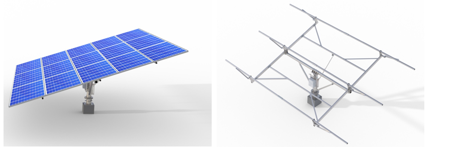
The MMS was conceived as a manually adjustable dual-axis tracker capable of optimizing solar capture while remaining rugged and low maintenance. The product design focused on:
• A compact footprint with optimized load paths
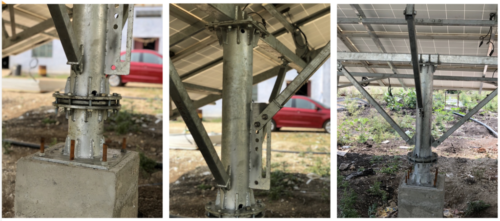
• A central vertical post with bearing assembly for rotation
• Primary and secondary support members distributing panel loads
• Adjustable angle mechanisms for tilt positioning
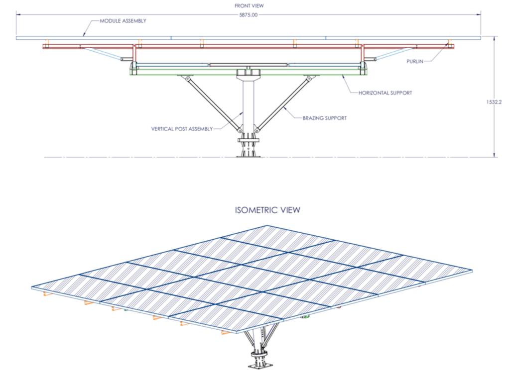
• Modular purlin and rafter assemblies for panel mounting
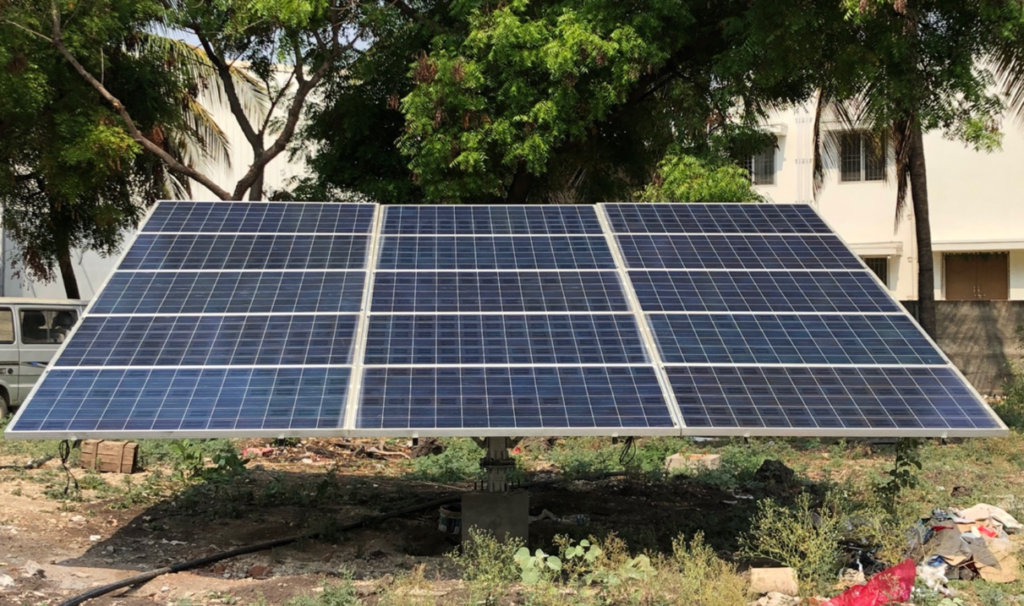
The resulting structure spans approximately 5.9 m × 5.0 m, supporting 15 modules while maintaining structural stability under wind speeds up to 150 km/h.
Design decisions were driven by real-world constraints:
• Ease of fabrication
• Fast installation
• Minimal component count
• Robust structural redundancy
This reflects a core philosophy of industrial product design: design for performance, manufacturability, and serviceability simultaneously.
Structural Validation Through FEA: Designing With Confidence
No modern structural product reaches fabrication without rigorous simulation. Finite Element Analysis (FEA) was used to validate structural integrity under both dead load and wind load conditions.
Dead Load Simulation Highlights
• Combined structural + panel weight evaluated
• Maximum deformation observed: ~21.5 mm at purlin leading edges
• Peak stresses remained within material yield limits
Wind Load Simulation Highlights
• Virtual wind tunnel modeling applied
• Maximum deformation under wind: ~16.4 mm
• Localized stress peaks evaluated and validated
• Structure confirmed safe up to 150 km/h wind speed
FEA insights enabled:
• Optimization of bracing members
• Stress redistribution
• Validation of bolt connections
• Reduction of overdesign weight
The analysis confirmed that the MMS remains structurally intact even under extreme loading scenarios — a critical requirement for outdoor solar infrastructure.
Prototyping: Bridging Digital Engineering to Physical Reality
Engineering validation must be proven in hardware. The MMS prototype phase focused on:
• Machining and structural fabrication
• Welding and roll-formed purlin manufacturing
• Assembly validation
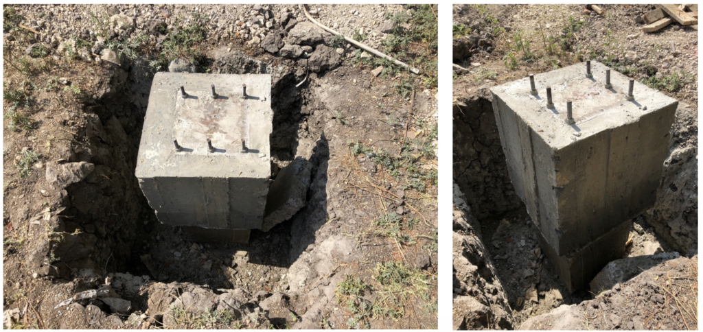
• Foundation interface testing
Key prototyping observations:
• Fabrication cycle per unit: ~4 days
• Installation time: ~2.5 hours
• Fastener count optimized for assembly efficiency
• Structural alignment validated in real conditions
The prototype stage provided essential feedback:
• Fitment improvements
• Assembly sequencing
• Field installation ergonomics
• Structural stiffness confirmation
This step ensured that simulation assumptions translated accurately into real-world behavior.
Manufacturing Engineering: Designing for Repeatability
The MMS manufacturing strategy emphasized:
• Standardized cutting and welding workflows
• Roll-formed purlin production
• Fixture-based assembly consistency
• Reduced fabrication complexity
Processes included:
• Laser cutting
• Vertical drilling
• MIG welding
• Grinding and finishing
Manpower planning and production sequencing were optimized to support scalable fabrication without compromising quality.
The result is a structure that is not only mechanically sound but also manufacturing-friendly, enabling cost-effective deployment across multiple installations.
Field Performance & Structural Reliability
Simulation and prototyping converge into one final goal: confidence in field performance.
Engineering validation demonstrated:
• Controlled deformation behavior
• Stress levels within safe limits
• Structural resilience under wind loading
• Effective load transfer through bracing systems
These findings confirm that the MMS delivers:
✔ Mechanical reliability
✔ Structural stability
✔ Long service life
✔ Installation practicality
— essential attributes for solar infrastructure exposed to continuous environmental stress.
Engineering Takeaway
The development of a Manual Dual Axis Solar MMS exemplifies how modern engineering integrates:
Product Design → Simulation → Prototyping → Manufacturing → Deployment
Each stage informs the next, ensuring that the final system is not only structurally sound but also manufacturable, installable, and scalable.
This methodology represents best practices in engineering product development — where analysis drives confidence, prototyping validates assumptions, and manufacturing strategy ensures repeatability.
Conclusion
From concept validation to real-world deployment, this Manual Dual Axis Solar MMS demonstrates how a structured engineering workflow transforms an idea into a reliable, field-ready asset. By tightly integrating design intent, FEA-driven validation, hardware trials, and manufacturing optimization, the project highlights the critical role played by Product design companies in India in delivering robust, scalable renewable-energy solutions. More importantly, the success of this system reinforces the value of Product Prototyping as a decisive bridge between digital engineering and on-site performance—ensuring faster development cycles, reduced risk, and long-term structural reliability in demanding outdoor applications.