Define. Conceptualize. Design
3d to 2d conversion services
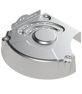
Sheet metal
Sheet metal design is the back-bone of Modern industry and it play a vital role in creating a fine product from Aerospace to Automotive to Consumer goods industry. Inorder to achieve a great design in sheet metal it is important to ensure the component design is established with clear sheet metal forming strategies.
Sheet metal design is a complicated procedure that involves bending and shape forming processes. There are different sheet metal techniques from formability studies, spring back effect and fatigue life of sheet metal components.
We evaluate sheet metal design through virtual testing prior to production and tooling. Our systematic approach for sheet metal components includes –
- Drafting and detailing of 2D and 3D sheet metal parts and assemblies
- 2D flat drawings and nesting drawings for sheet metal parts
- Development of fabrication drawings for large sheet metal assemblies including welding details.
- Sheet metal forming details to critical dimensions, relief cut, edge distortion, countersink forming, curls & hems, bend relief and bend radius.
To know more click here to connect or visit our Blog
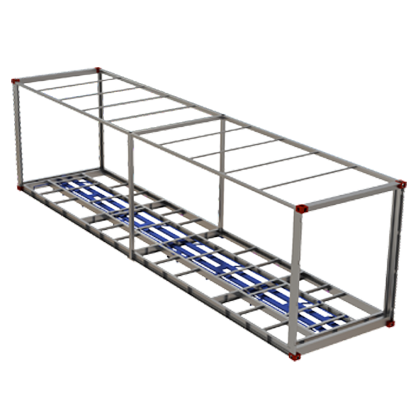
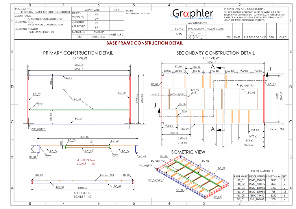
Structural Design
Structural design is the creation of large assemblies using formed members of various cross-sections which provides the intended stability, strength and rigidity of the structure. The main objective of a structural design is to develop a structural assembly capable of resisting all implied loads without failure during its service life.
In 3-D CAD, we help develop a preliminary design by conducting a study incorporating the intended design loads and functions with various standard members. It is then detailed and converted into assembly and fabrication drawings.
For structural design our design process includes –
- Feasibility study of using standard members
- Assembly check for fitment
- Welding details
- Assembly fabrication drawings
- Cut length drawings of all parts with punching and notching details
- Detailed Bill of materials (BOM)
- Quality assurance plan and fabrication checklist
To know more click here to connect or visit our Blog
Plastic design
Plastic design is the next big thing in development of Products. Today’s high-performance plastics and resins brings many benefits to the Industry that previously thought only metals could do. The durability of plastics can be found in many applications in every imaginable industry from Automotive, Medical to Plumbing and Aerospace.
A good design practice is essential to develop plastic components since it requires large tooling costs. When designing with plastic, the goal is to achieve an accurate design that functions well and cost-effectively manufactured.
To facilitate validation of the plastic design, we offer in-house rapid-prototyping services enabling us to create production quality prototype parts quickly before any tooling is made.
Read more about our systematic approach towards plastic design
To know more click here to connect or visit our Blog
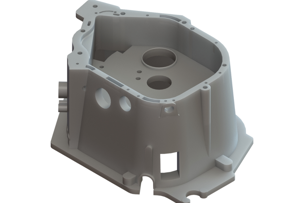
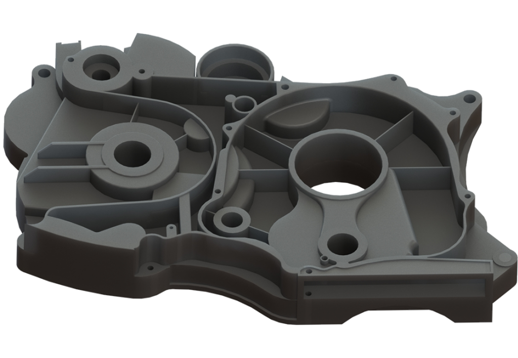
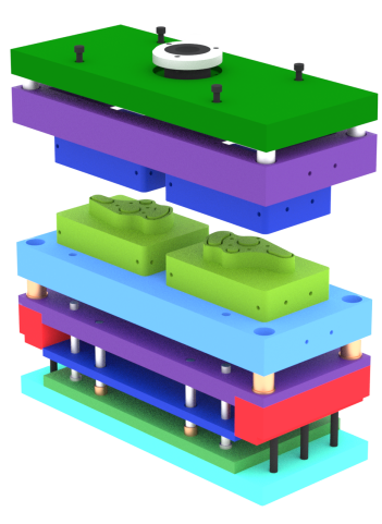
Mold design
Investment in tooling is substantial and a proper tool design and detailing is essential to create high precision molds. Our experienced tooling engineers will work to ensure that the tools are well designed and developed for maximum part-to-part repeatability and life cycle of tool.
Proper care and trail results has to be examined during mold design, some of the simple terminologies in mold design which we check during the design process –
- Gate type, size and its features
- Deciding a well-balanced gate position
- Proper gas venting during injection process
- Ensuring proper draft taper is kept which facilitates proper post-processing
To know more click here to connect or visit our Blog
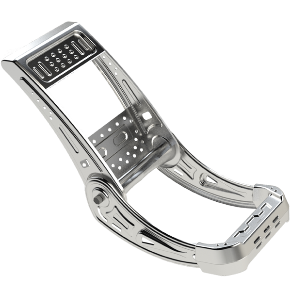
Body-in-White (BIW)
BIW refers to the body shell design of an automotive part. It is no different from a sheet metal welded structure. We perform advanced ready to manufacture digital mock-ups of BIW components with clear perspective of sheet metal forming process, surface modelling, BIW assembly procedures and GD&T.
Our approach towards BIW components includes –
- BIW design best practices
- Clean edge modeling technique
- Complex contoured depressions
- Creating flanges, beads and darts
- BIW component on drawing sheet
To know more click here to connect or visit our Blog
Multi-Body Dynamics
A system with multi-bodies consists of parts or assemblies connected together through links and joints that has relative motion. The study of Multi-body dynamics is the analysis of how the mechanical system works under the influence of forces in their respective links and joints. This type of study is called as forward dynamics. The inverse of which is the analysis to know the necessary force required to make the part or assembly move is called as Inverse dynamics.
Complex mechanical assemblies and moving parts often generate loads that are hard to predict, a dynamic system level analysis is required to understand how moving parts interact with each other and their environment.
In a brief, MBD is an analysis to evaluate how mechanical systems move under the influence of forces or conversely the load required to move the mechanical system in a particular manner.
To know more click here to connect or visit our Blog
Model base definitions
Model Based Definition sets data such as product models, dimensions, geometric tolerances, surface finishes, welding symbols, bill of materials (BOM), callouts, tables, notes, Meta properties, and other annotations within a 3D environment. Traditional 2D drawings are no longer needed. The intuitive and interactive 3D MBD provided by SOLIDWORKS serves multiple operational use cases, such as part and assembly engineering drawings, Request for Quote (RFQ), and Inspection Reports.
It also helps multiple departments and stakeholders across the operation, such as design, procurement, fabrication, assembly, quality, sales, marketing, clients, and suppliers.
To know more click here to connect or visit our Blog
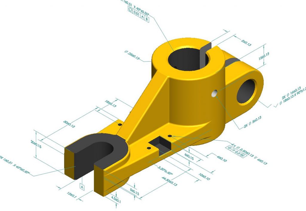
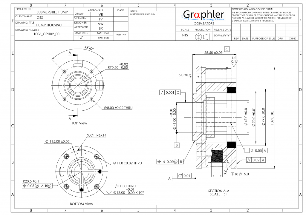
Machining or Production drawings
With the help of 3D CAD, which has been checked for fitment and assembly. We will be able to accurately replicate the production drawings for the machine shop. Our machining drawings includes the following –
- Sectional and detail views
- Thread patterns
- Detailed GD&T
- Surface finish details
- Post – machining operation details
We can help you with your next project, speak with us.
Design for Manufacturing and Assembly (DFMA)
DFMA is a practice followed to design a component or an assembly with manufacturing in mind so they can be developed with least efforts and with fraction of development cost, makes the quickest transition into production, be assembled with minimum cost and time, have a desired level of quality and satisfy customer’s needs.
We incorporate DFMA early in design process to shorten Product development time and ensure smooth transition into manufacturing leading to shorten time-to-market. By incorporating DFMA products are developed to quickly assemble from fewer standard parts. DFMA in turn also helps to create a broader product line by creating commonality with other designs.
To know more click here to connect or visit our Blog
Fabrication drawings
Inorder to enable production, you must have clear, precise drawings that are easy to interpret for laymen. Once 3D CAD model is checked for fitment and assembly it is then exported for conversion of 2D drawing sheets required for fabrication of steel structures and large assemblies.
Accurate drawings are less likely to be mis-interpreted, which mean they are less likely to cause errors during fabrication of the assembly. A set of drafting standards should be followed to produce –
- Stack-up tolerances
- Sectional details
- Detail views
- BOM
- Weldments
- Cut lengths and Part drawings
We can help you with your next project, speak with us.
To know more click here to connect or visit our Blog