
The valve body or Pressure vessel will be analyzed for a given load condition as per ASME Design by analysis for pressure vessel. The sections will be linearized to define the membrane and bending stress to compare with the ASME allowable stress, according to the procedure described in ASME VIII Div.2 2007. The numerical analysis and loading conditions will be performed in-line with the ASME 5.1.2 Numerical analysis and 5.1.3 loading conditions.
The following parameters will be calculated from the analysis as per ASME VIII Div.2:
- Primary membrane stress (Pm)
- Primary membrane plus bending stress (Pm + Pb)
- Equivalent stress (Pl + Pb)
- Total stress (Pl + Pb + Q)
These stress values will be compared against the ASME allowable stress limits to ensure the structural integrity of the design.
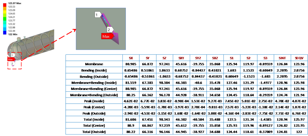
Post-Process techniques – Stress linearization and Stress Classification Lines
The Stress Linearisation Technique as per ASME Section VIII Division 2 is a critical method for Finite Element Analysis (FEA) of pressure vessels. In cases where failure modes are due to Plastic Collapse or Fatigue/Cyclic Loading, this linear-elastic approach is outlined in Part 5 of the code.
The rationale behind this technique is that not all stresses will contribute equally to the plastic collapse of the pressure vessel. As such, a simple stress-at-a-point limit is not a meaningful metric. The Stress Linearisation method allows for the separation of membrane, bending, and peak stresses, providing a more nuanced and accurate assessment of the structure’s integrity.
This formal approach is essential for ensuring the safe and reliable design of pressure vessels in accordance with the rigorous ASME standards. By properly applying the Stress Linearisation Technique, engineers can make well-informed decisions and mitigate the risks associated with plastic collapse and fatigue failure modes.
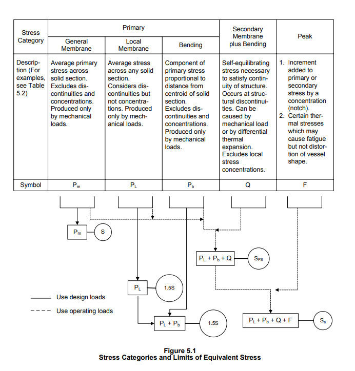
Therefore, the stresses are calculated in FEA in specific locations called Stress Classification Lines (SCL), which are further linearized and classified by this technique. Then, those linearized and classified stresses at each location or part are compared to appropriate allowable stress limits. This is the general basis behind what is known as the Hopper Diagram shown below –
Graphler Technology is one of the leading product design companies in India. We have experts in FEA services and also we are specialized in CFD Consulting Services , 2D to 3D Conversion services, engineering animation services etc.