RENEWABLE ENERGY / SOLAR & STORAGE
Solar engineering. From structure to system.
Mounting structures. Moving arrays. Mobile generation. Power infrastructure.
Our solar work connects mechanical design, structural and thermal analysis, detailed engineering and prototype development—from the members beneath a module to the equipment inside an energy storage container.
Explore our solar workProject-led engineering by Graphler Technology Solutions
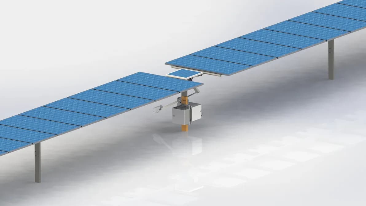
01 / SINGLE-AXIS TRACKER
DESIGNANALYSEDETAILDEVELOP
THE SOLAR PORTFOLIO
Engineering across the solar system.
Every application brings a different mechanical challenge. A rooftop system must balance restraint and roof interfaces. A tracker has to carry wind loads while moving reliably. A mobile generator must deploy from a compact transport envelope. An inverter station or BESS must bring structure, equipment, access and ventilation together. Our work spans each of these challenges.
01 / MODULE MOUNTING SYSTEMS
The structure behind the array.
Ground, roof and canopy applications—developed around the way modules are supported, assembled and maintained.
GROUND-MOUNT MMS
From module layout to a buildable structure.
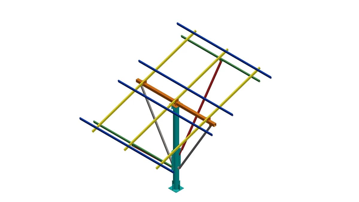
Our ground-mounted module mounting structure work brings together the array geometry, supporting members and connections. We develop the relationship between purlins, rafters, bracing, posts and foundation interfaces, translating a module layout into a coordinated mechanical assembly.
The engineering extends into the details that make the structure practical to build: member interfaces, hole positions, bolted joints, assembly drawings and bills of materials. Structural studies examine how module weight and wind loading pass through the frame and its connections, supporting review of member sizes and local details.
- Array and supporting-frame development
- Member, connection and foundation-interface detailing
- Fabrication documentation and structural assessment
ROOFTOP & BALLAST-TYPE MMS
Resolve the roof interface. Simplify the assembly.
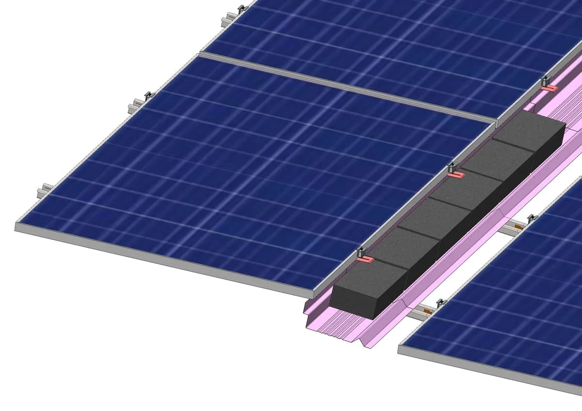
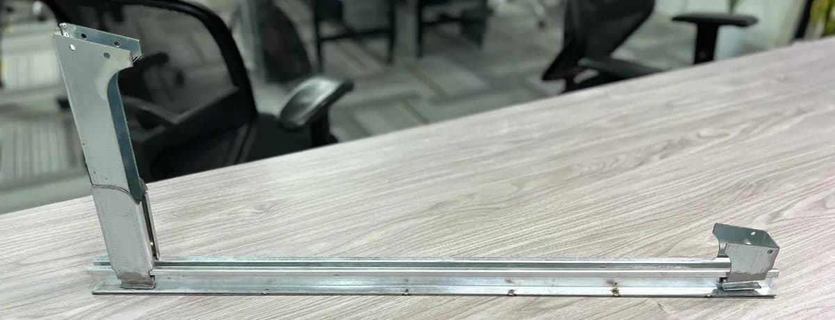
For rooftop solar, our work has included ballast-type mounting concepts, component development and prototype evaluation. The documented system studies bring rails, splices, module supports, adjustable brackets and clamps into a repeatable assembly, with ballast trays and wind deflectors developed as part of the structure.
Detail development considers how components are formed, stiffened, joined and reached during installation. Prototype records connect those design decisions to fabricated rails, supports and trays. Rail-fitment and tooling feedback informed subsequent details. Uplift-test development adds a physical route for investigating the assembly and its restraint arrangement.
Ballast, module support and the interface to the roof are considered together, so the mounting concept can be developed against the requirements of the particular application.
- Rail, support, clamp and splice design
- Integrated ballast trays and wind deflectors
- Prototype fabrication and uplift-test development
SOLAR CARPORTS
A canopy that works as a parking space.
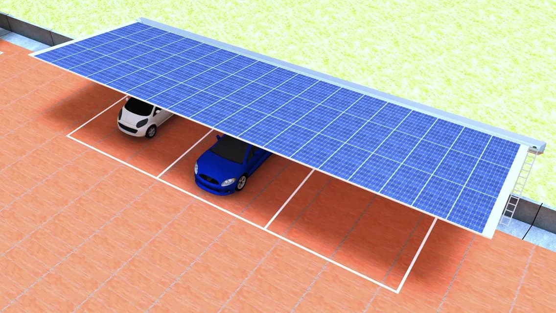
Carport development brings energy generation into a space used every day. Our studies explored alternative column and canopy arrangements, modular connections, module rails and digital assembly sequences.
The detail work connects the structure to practical needs below and above the canopy: parking access, bolted fit-up, cable routing, cleaning access and central drainage. Structural investigation of the support and upper connector supports further design review.
- Canopy concepts
- Connection design
- Assembly planning
02 / TRACKING SYSTEMS
Engineer the movement. Understand the loads.
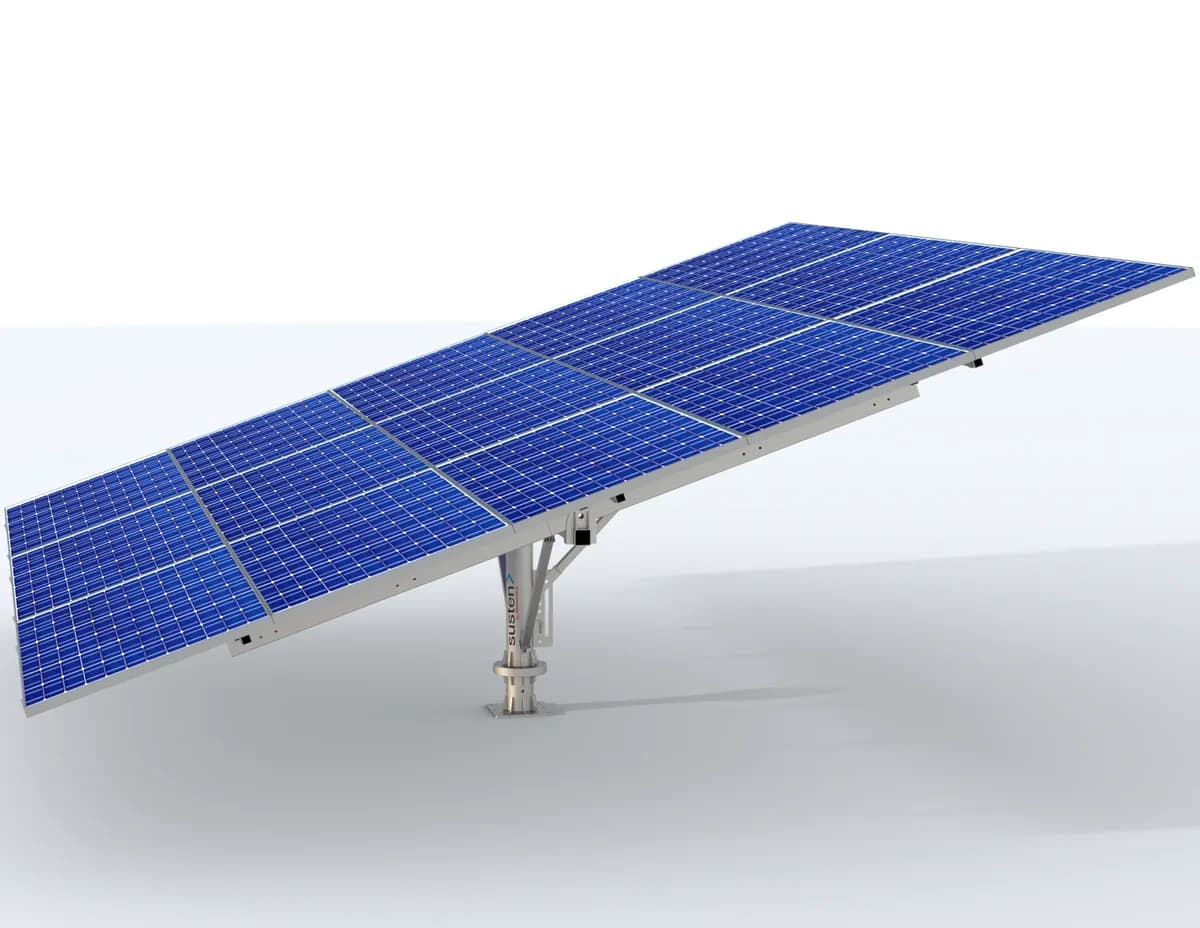
Tracking structures bring motion and structural behavior into the same engineering problem. Our portfolio covers single-axis arrays and manually adjustable dual-axis mounting systems.
SINGLE-AXIS TRACKERS
The array, its supports and the wind around it.
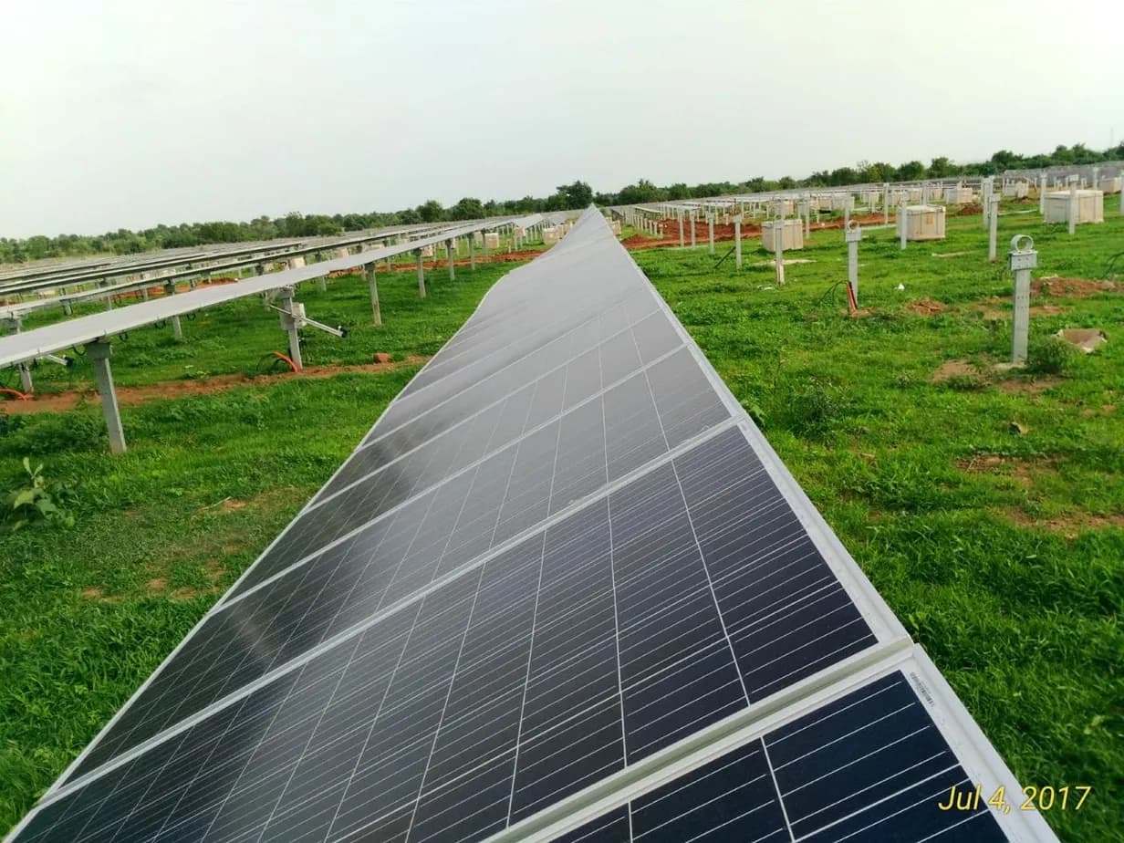
Our single-axis tracker work includes structural modelling and wind-load assessment of the module array. Computational fluid dynamics establishes how pressure varies across the panels at a defined tracker angle and wind condition; those loads inform the structural assessment.
This connects the aerodynamic behaviour of the array to the response of its supporting structure. Component studies examine rails, bearing assemblies and torque-tube connections, making local load paths and critical interfaces visible alongside overall deformation. Each assessment is tied to its operating or stow configuration.
- Wind-pressure assessment
- Structural analysis
- Connection review
DUAL-AXIS TRACKERS & ADJUSTABLE MMS
Rotation and tilt, built into the support.
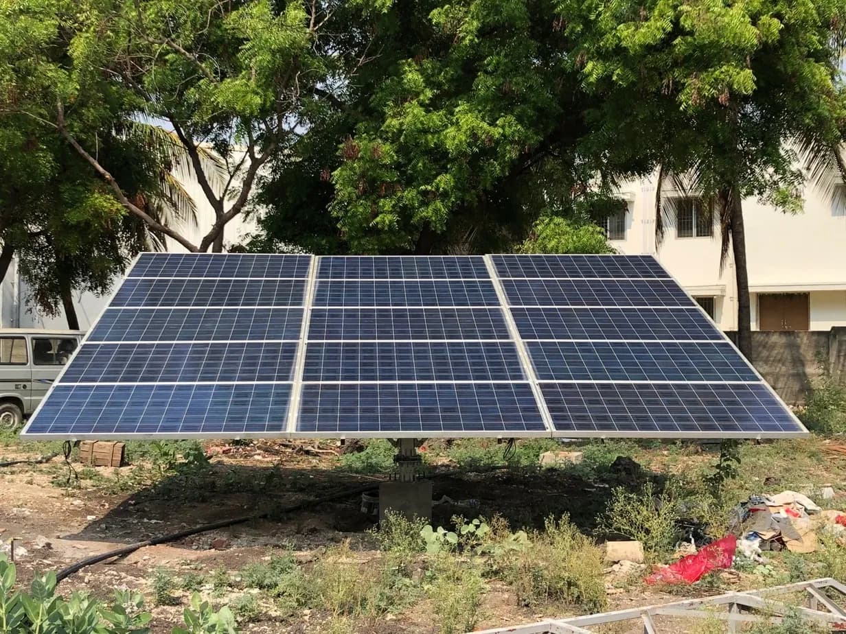
For a 15-module solar pumping application, we developed a manually adjustable structure with rotation and tilt incorporated into a central support. The design coordinates the bearing arrangement, adjustment plates, bracing, rafters and formed purlins.
The project progressed through detailed mechanical design, fabrication information, foundation-interface preparation and a physical mock-up. Wind-load evaluation and structural analysis added a documented basis for reviewing frame movement and critical connection regions.
- Manual rotation & tilt
- Bearing & adjustment details
- Physical mock-up
AT THE CONNECTION
Small details carry the whole array.
Bearing flanges, angle plates, bracing joints and module supports define how the structure moves and how loads travel back to its base. Developing these interfaces is central to turning the tracking concept into a complete mechanical system.
03 / MOBILE & INTEGRATED SOLAR
Solar that opens up new applications.
Compact in transport. Deliberate in deployment. Our product-development work brings solar arrays into mobile equipment and containerized systems.
MOBILE SOLAR GENERATORS
A complete mechanical development programme.
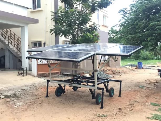
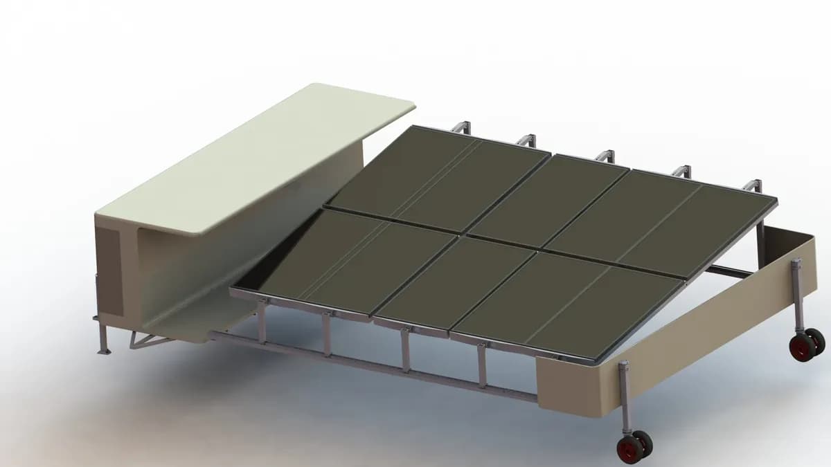
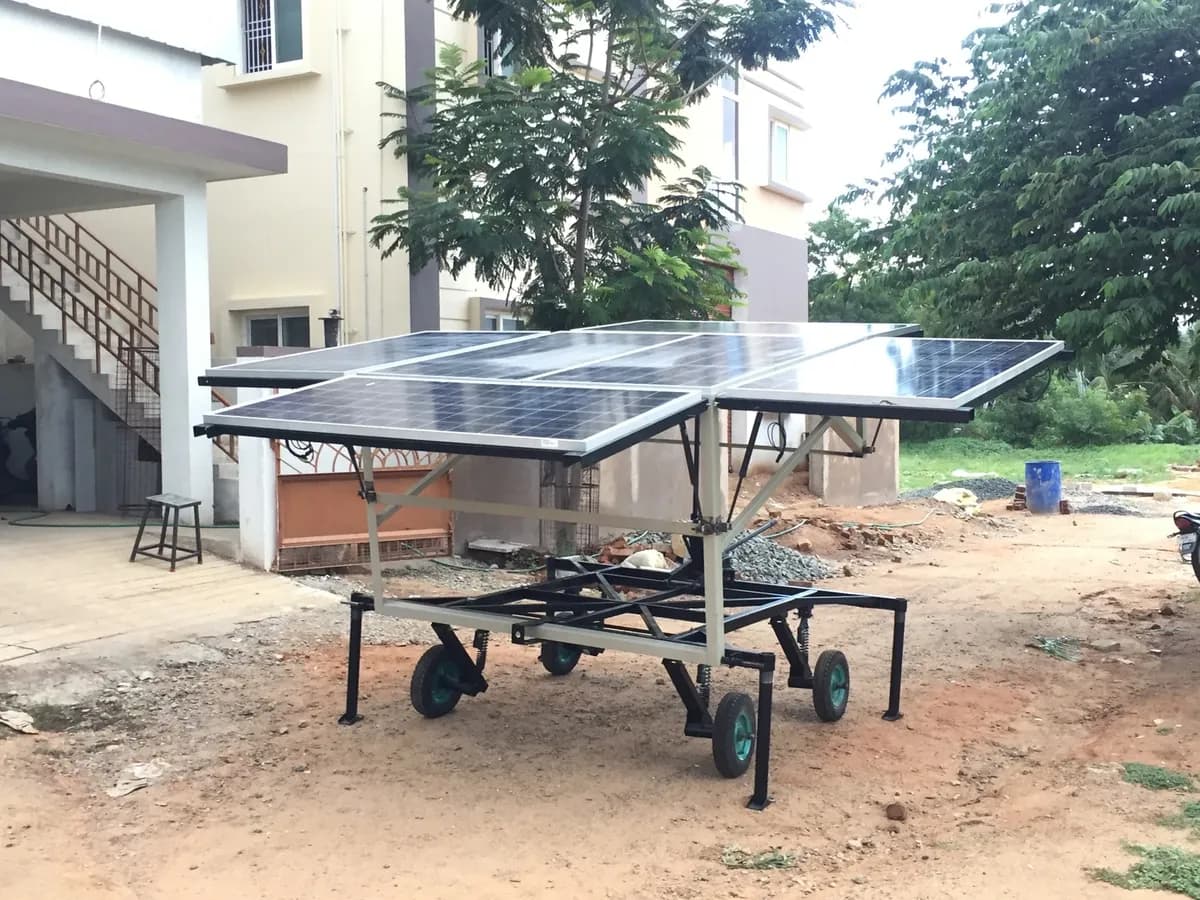
Our mobile solar generator work spans multiple concept and prototype iterations. The challenge is to bring a useful module area into a transportable product while coordinating the chassis, running gear, enclosure, panel frames and deployment mechanism.
Concept studies explored folding, sliding and guided-expansion arrangements, with tilt, locks, supports and access developed for the relevant version. Detailed reviews examined panel-frame construction, hinges, brackets, bracing and fabrication methods.
Physical prototype observations fed back into the development of the chassis and suspension interfaces. Structural studies examined defined transport and deployed configurations, connecting mechanical design decisions to the loads the assembly was intended to carry.
- Concept selection and deployment mechanisms
- Chassis, suspension and enclosure integration
- Prototype learning and structural evaluation
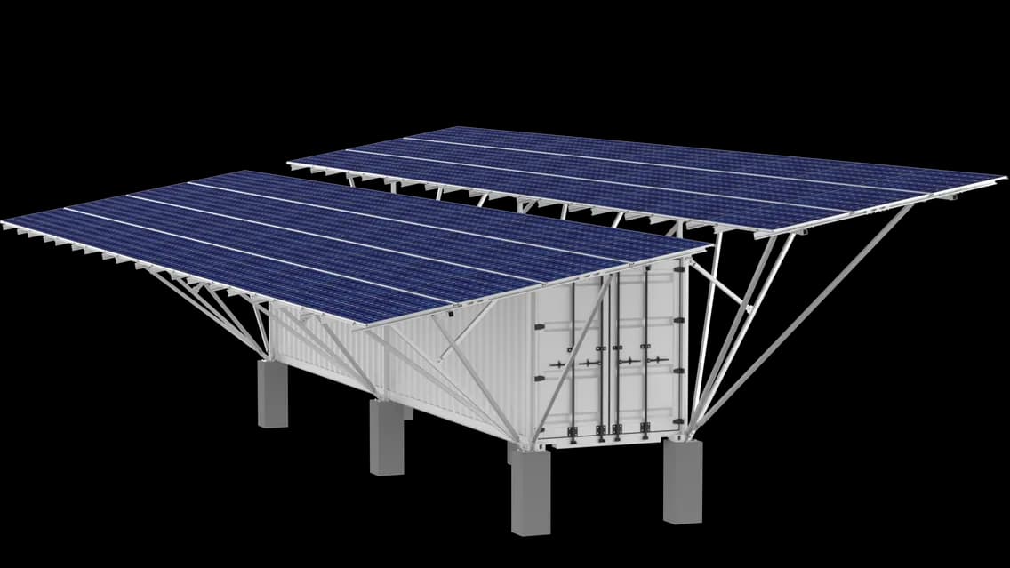
CONTAINERIZED SOLAR & HYBRID SYSTEMS
Bring the array and equipment into one architecture.
Our containerized hybrid microgrid work coordinates a solar support structure with the container and its internal equipment spaces. Design records cover panel-support arrangements, battery and inverter areas, partitions, equipment racks, cable routes, ventilation ducts and service access.
Structural and thermal studies support review of the integrated design. Drawings, parts lists and assembly information connect the external solar structure with the equipment layout inside, giving the mechanical package a consistent basis for further development.
04 / POWER INFRASTRUCTURE
Beyond the modules. Inside the system.
Inverter stations and battery storage need a coordinated mechanical platform around the electrical equipment. Our role brings the structure, enclosure, equipment interfaces and service needs together.
INVERTER STATIONS & EQUIPMENT SKIDS
Make the equipment work as an assembly.
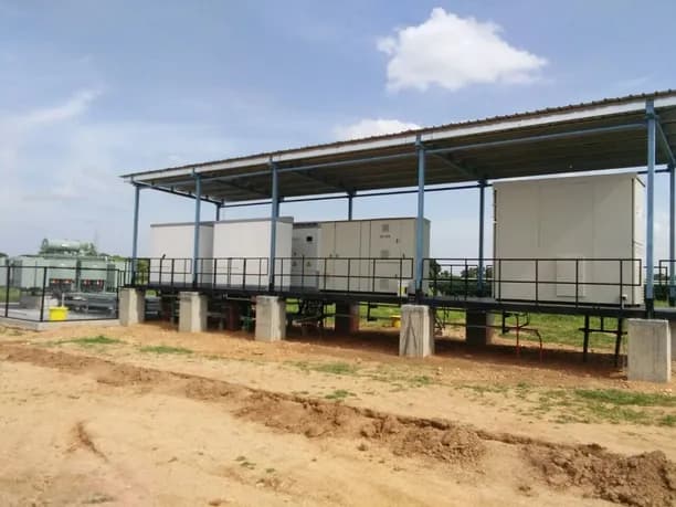
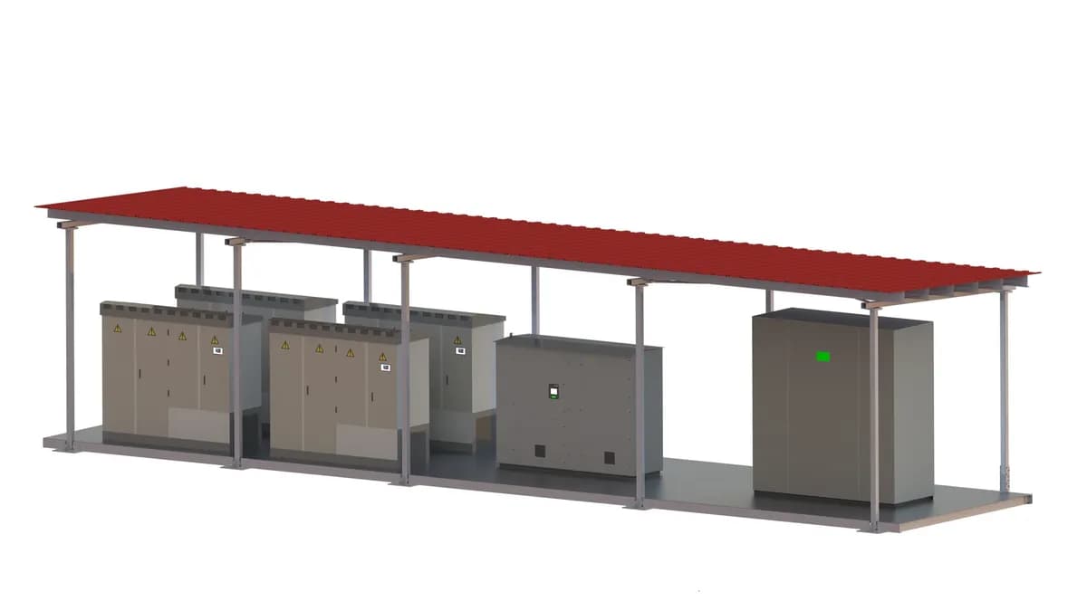
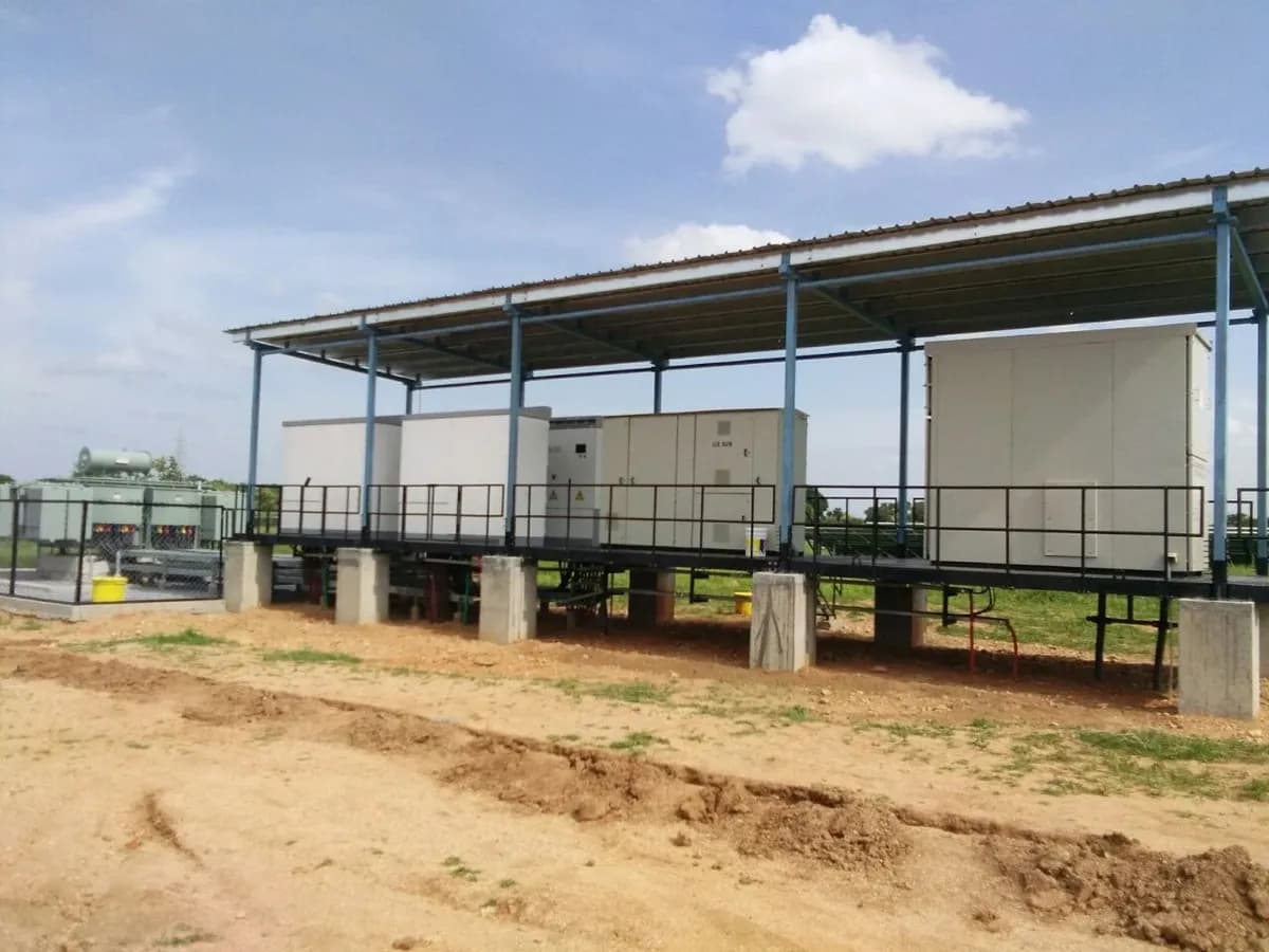
Our inverter-station work extends from open equipment skids to enclosed container arrangements. We coordinate the load-carrying base, superstructure, equipment positions, working clearances and access with floor and roof assemblies, cable routes and service openings.
Ventilation and duct studies examine how cooling air reaches the equipment and how heated exhaust leaves the enclosure. Structural assessments address relevant operating, wind, lifting and transportation conditions, with the study scope set for the particular station configuration.
Original models, detailed drawings and integration records connect the selected arrangement to fabrication and assembly. The work includes connection details and practical interfaces such as equipment fixings, stairs, handrails, gutters and foundation connections.
- Container and skid architecture; equipment integration
- Ventilation, duct and structural studies
- Fabrication drawings and assembly documentation
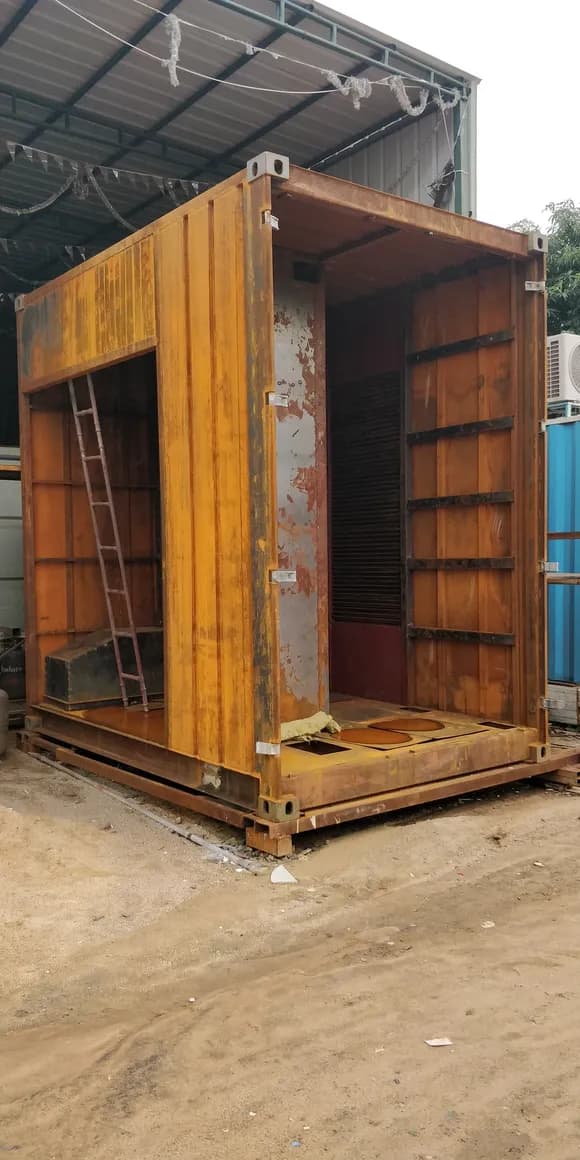
BATTERY ENERGY STORAGE SYSTEMS
Design the container around the equipment.
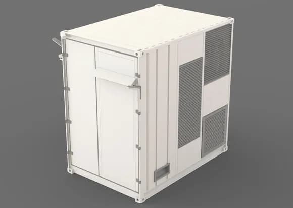
Our BESS work covers the mechanical development of a compact containerized energy storage system. The scope connects the base and superstructure with battery and equipment spaces, partitions, doors, cable trays, ventilation openings and maintenance access.
Equipment packaging brings purchased batteries, power-conversion equipment, transformer, air-conditioning and fire-system interfaces into the overall arrangement. Structural studies review defined support, payload, lifting and wind cases. Thermal and airflow studies examine the relationship between heat sources, room conditions and the proposed ventilation and cooling arrangement.
The development continues into fabrication drawings and workshop coordination, including access to fasteners, cable-gland details, equipment fixing and local reinforcement. These practical interfaces link the digital design to the physical build.
- Container structure and equipment packaging
- Structural, thermal and ventilation studies
- Fabrication detailing and workshop support
THE ENGINEERING APPROACH
Connected work, from brief to build.
The deliverables vary by project. The consistent thread is a mechanical design that can be understood, assessed, detailed and taken forward by the next team.
- 01
Define & develop
Translate the module arrangement, operating needs, transport limits and equipment envelope into concepts. Resolve interfaces and compare assembly approaches before committing to detailed geometry.
- 02
Analyse & refine
Use structural, wind-flow and thermal studies where they answer the project’s questions. Review deformation, local stresses, pressure distribution and equipment temperatures against the defined design basis.
- 03
Detail & document
Develop the assemblies, component drawings, connection details and bills of materials. Coordinate fabrication, fastening, installation sequence and service access within the mechanical package.
- 04
Prototype & learn
Where included in the scope, connect the design to prototype manufacture, assembly and physical evaluation. Record fit-up, access and handling observations and feed them into the next design iteration.
WHAT THE WORK CAN INCLUDE
- Concept studies
- Product CAD
- Structural assessment
- Wind & thermal studies
- Detailed drawings
- Bills of materials
- Prototype support
YOUR NEXT SOLAR PROJECT
Start with the application. Build the engineering around it.
Bring us the system you need to develop—a mounting structure, tracker, mobile generator, inverter station or storage enclosure. We can define the mechanical scope around your requirements and the stage your project has reached.
A USEFUL STARTING BRIEF
- 01The application, location and operating conditions
- 02Module or equipment layout and available space
- 03Transport, installation and maintenance requirements
- 04Current drawings, design questions and required deliverables
An editable text checklist to help prepare your enquiry.