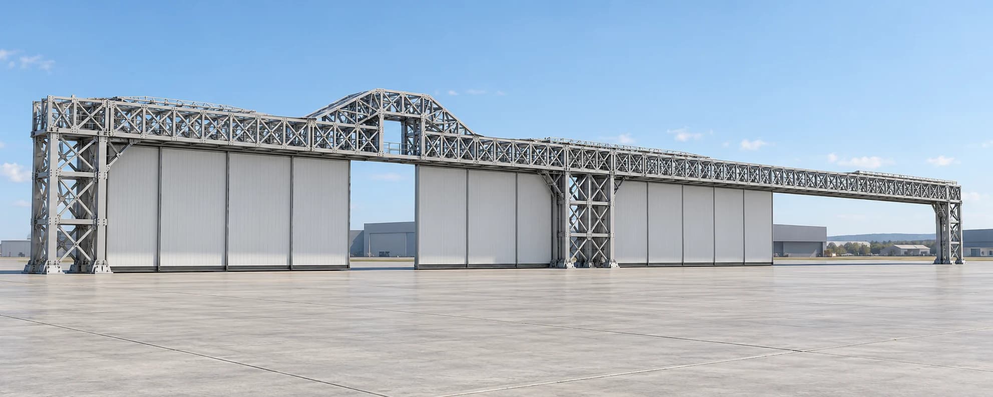
Structural FEA of a hangar-door outrigger
CAD development, dead-load response and wind-load assessment
STRUCTURAL DESIGN & FINITE ELEMENT ANALYSIS
Structural FEA of a hangar-door outrigger
- Requirement
Support a very wide door frontage
Develop the truss, column and rail arrangement and understand how the structure responds to its dead load, top tracks and wind loading
- Challenge
Trace global and local response
Long truss spans, cantilevered supports and connection details create different stiffness demands across the two hangar openings
- Deliverables
Design & assessment evidence
Assembly drawings, column-development studies, deformation and stress contours, critical-location review, and rail/foundation coordination
01 / PROJECT ARCHITECTURE
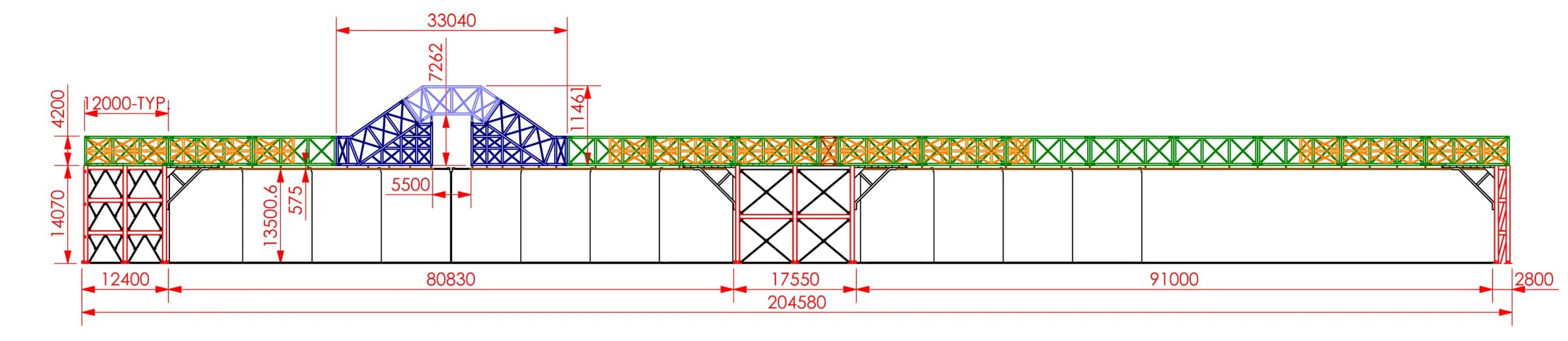
A continuous structure across two hangar openings
The numerical history places the result snapshots on the same timeline. Temperature and CO peak at the assumed 25-minute fire cut-off, then decline as the source stops and ventilation continues
- Overall assembly length
- 204.58 m
- First opening dimension
- 80.83 m
- Second opening dimension
- 91.00 m
02 / CAD DEVELOPMENT
The column and bracing arrangement evolved together
The February drawings record a change in the tower configuration. The study updates the column sections and replaces the earlier beam-bracing arrangement with X-braced panels, while retaining the truss and rail interfaces within the complete assembly
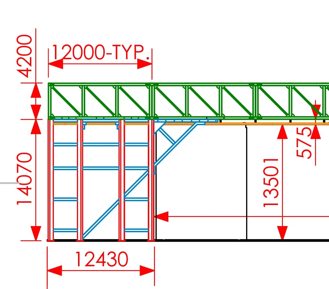
Earlier column arrangement
The 15 February drawing shows NPB 500 × 200 × 12 columns with NPB 300 × 200 × 9.4 beam bracing
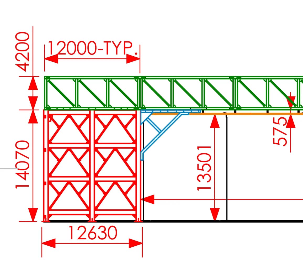
Revised X-braced arrangement
The 16 February drawing shows NPB 600 × 220 × 9.8 columns and ISA 150 × 150 × 10 angle bracing
These drawings document configuration changes. The supplied analysis does not establish an accepted reanalysis of the later April assembly
03 / ANALYSIS BASIS
Two load cases examined the original support system
The structural study first assessed the dead load and top tracks, then added wind loading. It reviewed the complete frontage before examining individual column assemblies, braces and truss connections. This linked movement across the long spans to the local details carrying those loads
| STUDY CASE | ASSESSMENT FOCUS |
|---|---|
| Case 1 / dead load + top tracks | Truss deflection, column movement and connection stress |
| Case 2 / dead load + wind | Lateral stiffness and the demand on the support strategy |
- Steel density
- 7,850 kg/m³
- Young’s modulus
- 200 GPa
- Poisson’s ratio
- 0.29
The report identifies mild structural steel and a yield-strength range of 275–351 MPa. It does not assign one grade or allowable stress to every component
04 / DEAD-LOAD RESPONSE
Different movement across the two hangar spans
Under dead load and top-track loading, the report identifies approximately 83 mm of deformation on the wide-body hangar side and 126 mm on the narrow-body side. The whole-model contour records a peak of 126.736 mm. These results establish the baseline for the component review
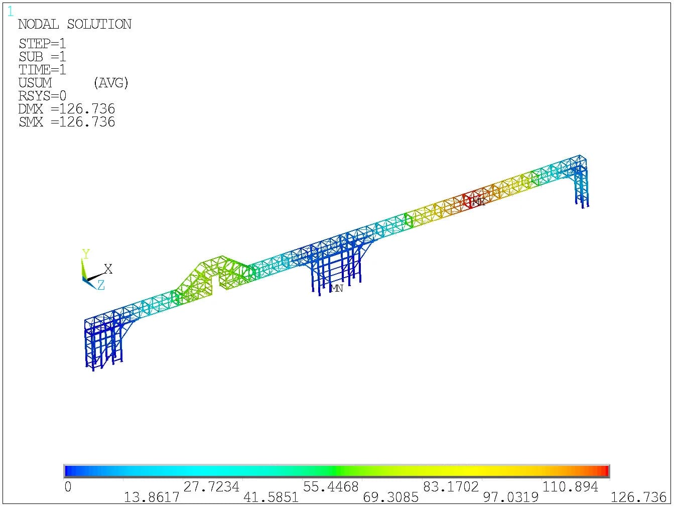
Response across the complete frontage
The original isometric result relates the long trusses, raised opening and three support groups. Colours show displacement magnitude in mm
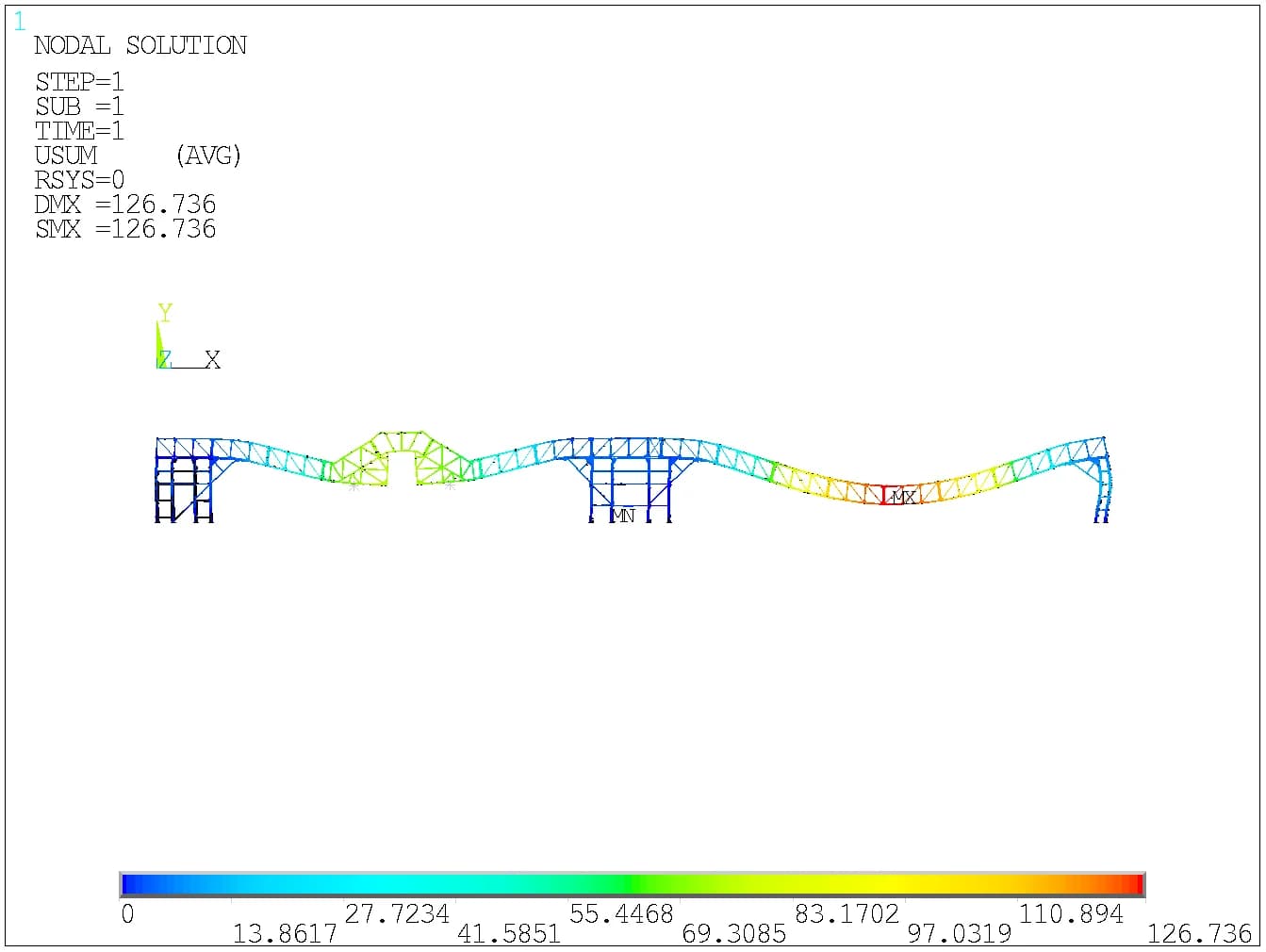
Movement along the truss system
The companion view makes the variation along the two spans visible. Local column results are reviewed separately from the global maximum
05 / COLUMN RESPONSE
Cantilever movement varied between the supports
The end assemblies transfer load through cantilevered upper members into the vertical columns and braces. Their movement differs from the overall truss displacement. Examining each support separately exposed the locations that deserved closer connection-level assessment
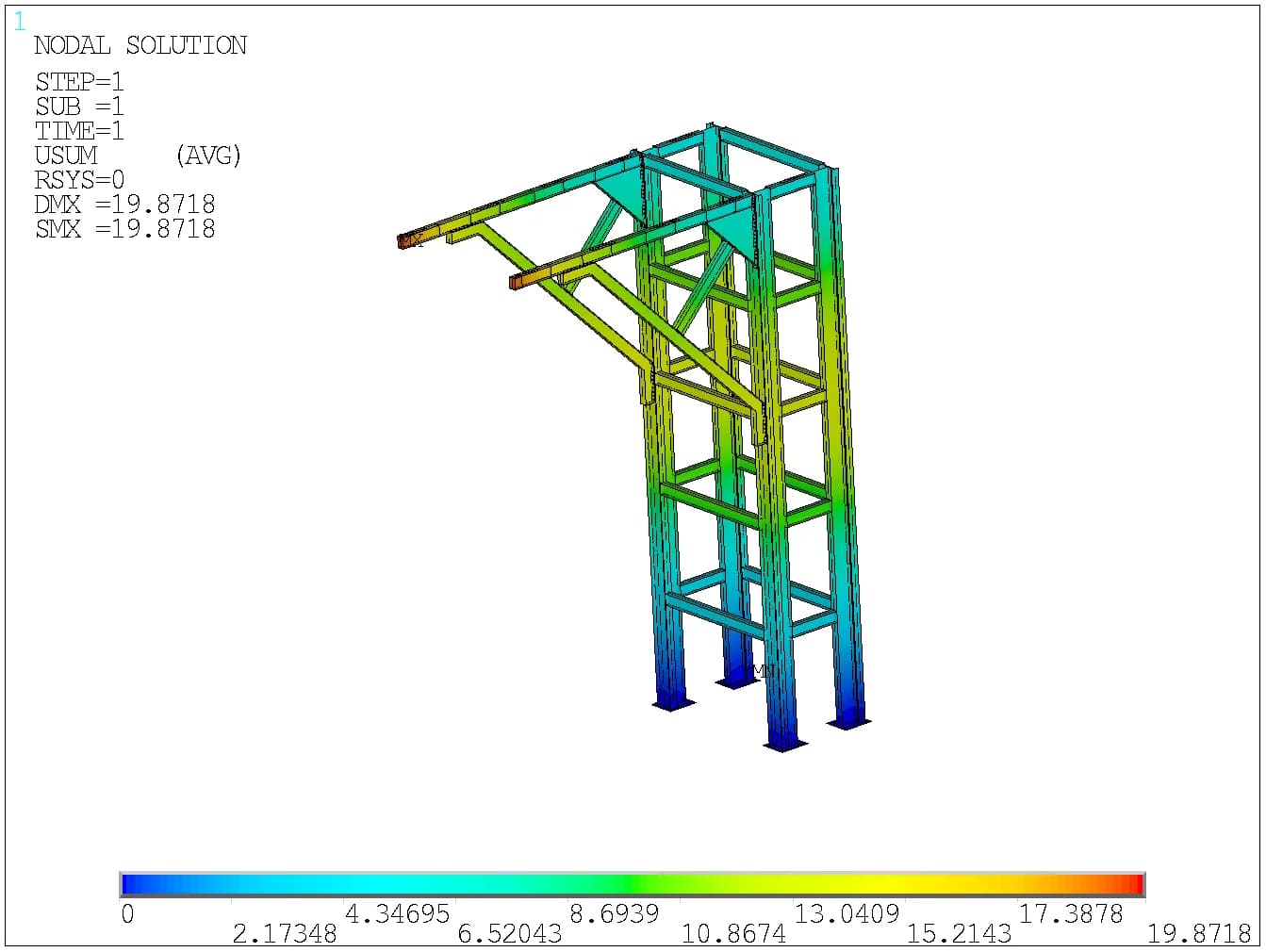
Narrow-body hangar end column
The report identifies 19.87 mm at the leading end of the cantilever near the paint-hangar side
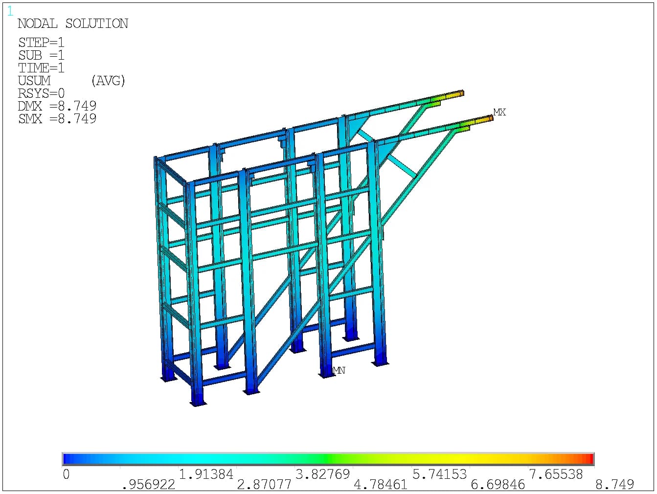
Wide-body hangar end column
The corresponding left end assembly shows 8.74 mm, again concentrated towards the cantilever’s leading end
| ASSEMBLY | REPORTED DISPLACEMENT | REVIEW LOCATION |
|---|---|---|
| Centre column | 7.776 mm | Movement towards the NBH side |
| NBH corner column | 19.87 mm | Leading end of the cantilever |
| WBH corner column | 8.74 mm | Leading end of the cantilever |
Rounded values follow the report annotations. All three belong to the base-case dead-load and top-track assessment.
06 / LOCAL STRESS REVIEW
Connections became the focus of the design review
The stress plots locate concentrations around member junctions, bolted regions and brace-to-column interfaces. The report specifically calls for redesign of the narrow-body hangar corner column. The close-up views connect that finding to individual joints rather than only the overall frame response
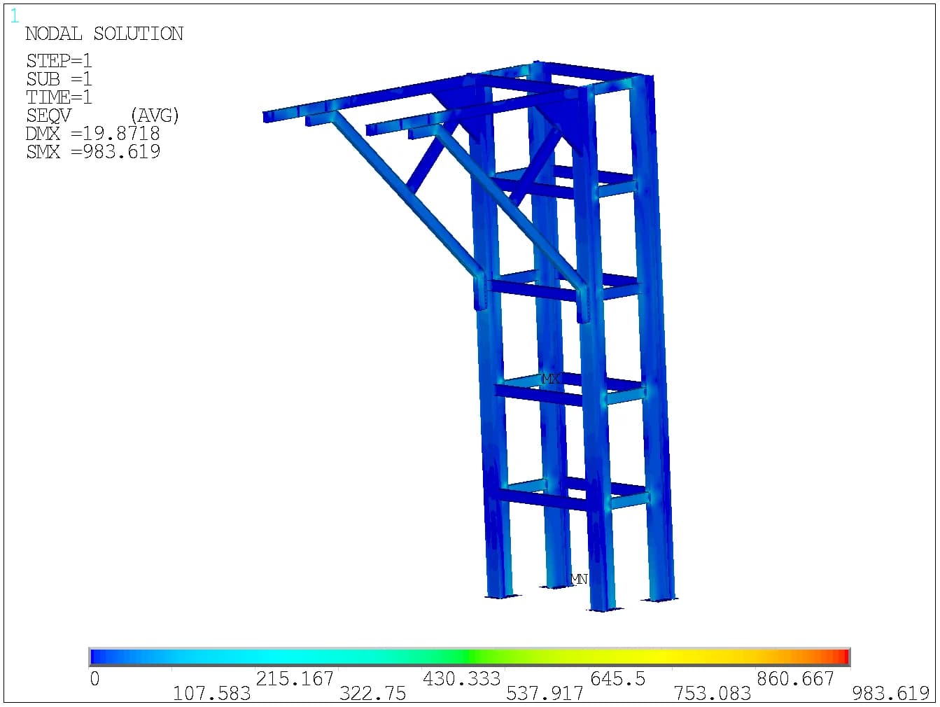
NBH column assembly
The full stress field identifies the critical end support. Its local computed peak is above the material-strength range stated in the report
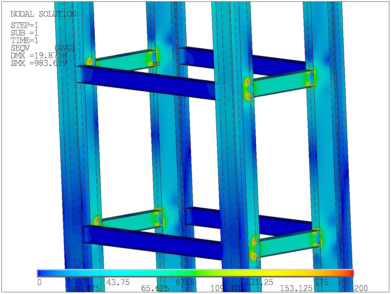
Member-to-column junctions
The enlarged view exposes concentrated response at the connection regions. These details form part of the redesign review
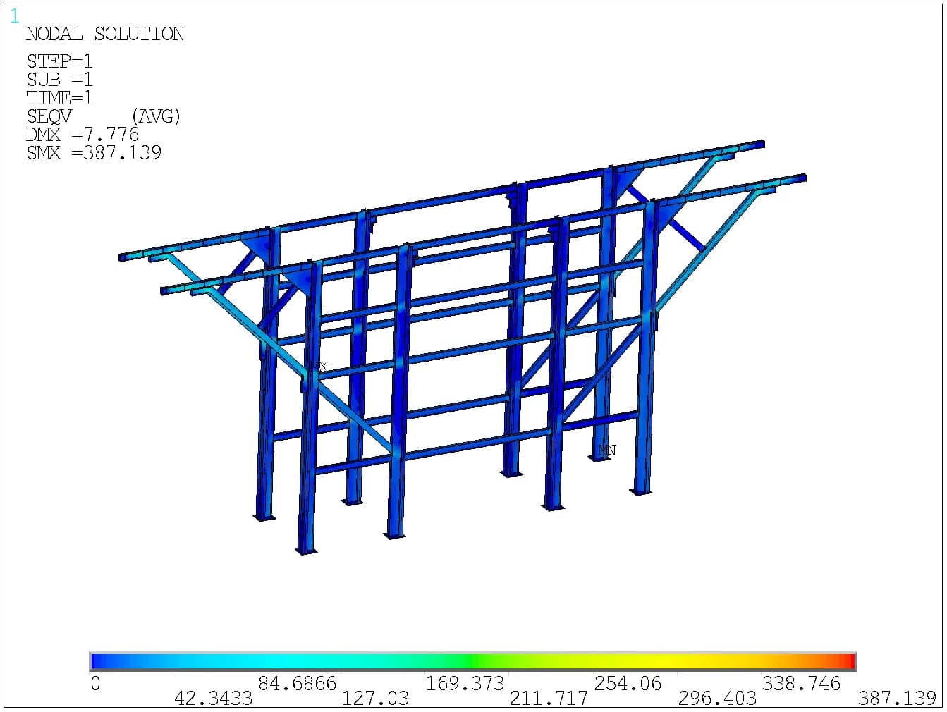
Centre support and bracing
The centre assembly also develops local concentrations around its brace and column interfaces as it transfers load from the adjacent spans
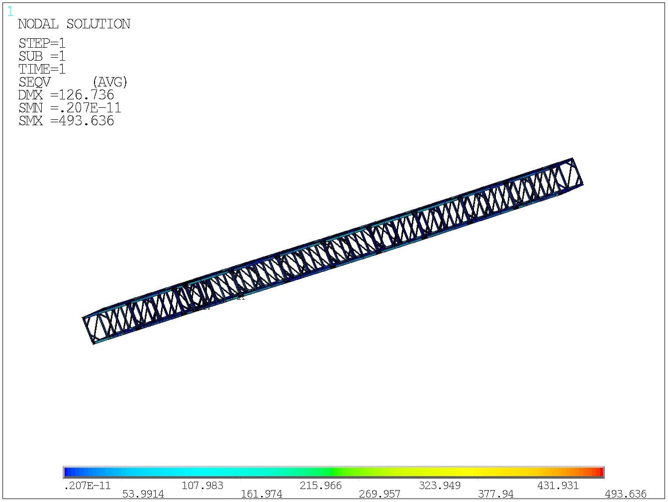
Truss members and joints
The truss result extends the review to the load path above the openings, including connection regions and local changes in stiffness
Stress figures are in MPa. Some original detail plots cap the colour scale at 200 MPa while retaining higher computed maxima in their labels. The scale ceiling is not an acceptance limit
07 / WIND-LOAD STUDY
Wind exposed the need to revisit lateral support
The wind study applies a reported speed of 120 km/h (33.3 m/s), with a dynamic pressure of 683.3 Pa. Loads act across the hangar-door areas defined in the report. Adding this lateral demand reveals how strongly the baseline response depends on the stiffness of the column and support arrangement
| REPORT ZONE | IMPACT AREA | APPLIED WINDFORCE |
|---|---|---|
| Wide-body hangar | 1,099.3 m² | 751.18 kN |
| Narrow-body hangar | 1,224.0 m² | 836.40 kN |
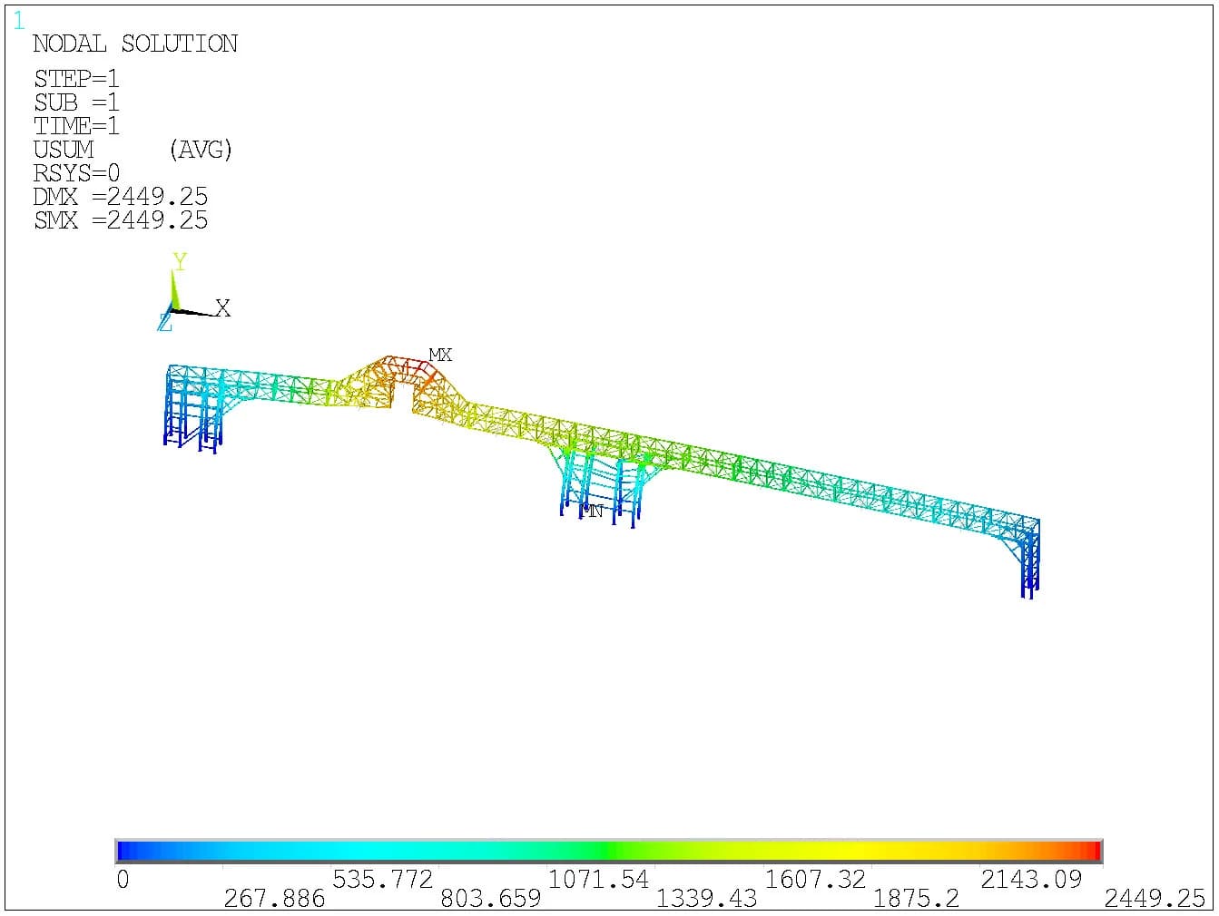
Large computed lateral movement
The wind case gives a peak displacement of 2,449.25 mm near the tail-gate region, identifying a major stiffness issue in the baseline configuration
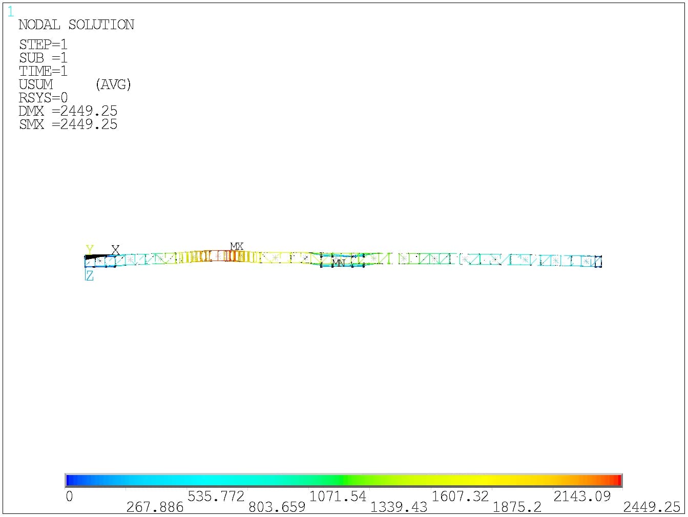
Support demand in plan
The plan view shows the truss movement relative to the column groups. The report recommends revisiting the columns or connecting supports to the main hangar
This is the computed response of the original study model and a basis for redesign. The supplied report does not establish the performance of a completed, revised structure
08 / DETAIL DEVELOPMENT
Rail and base connection details
The drawing package develops the details around the main structural members. Rail-support spacing controls the relationship between the upper truss and the door guides, while base-plate geometry sets out the connection between the steel towers and the civil works
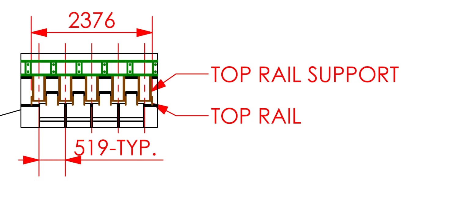
Upper rail coordination
The section shows the top rails and their supports across the truss width, including the repeated spacing used in the assembly
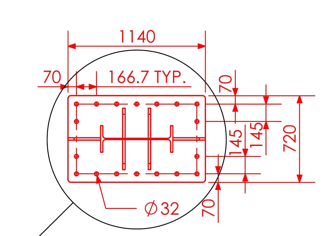
Base plate and anchor layout
The foundation detail defines the plate outline and bolt-hole pattern for coordination with the supporting civil structure
09 / FOUNDATION COORDINATION
Three support groups and a continuous rail frontage
The April foundation drawings coordinate the tower groups, anchor locations and lower rails along the frontage. Plan views establish the setting-out geometry, while longitudinal sections relate the deeper support blocks to the continuous rail and ground interface


Original foundation coordination drawings. Dimensions describe the documented geometry. The provided package does not establish a separate soil or foundation-capacity assessment
A clear basis for structural redesign and coordination
The assessment traced the governing behaviour from the long trusses into the cantilevered end supports and local connections. It identified the narrow-body hangar corner column and the lateral support strategy as priorities for further design work Together, the analysis and drawing package provided a documented basis for reviewing the steelwork, rail interfaces and foundation arrangement. The record supports a design-development outcome. Final acceptance of the later geometry is not demonstrated in the supplied analysis