ENGINEERING METHODS CASE STUDY/STRUCTURAL ANALYSIS
Nonlinear FEA: choosing the right modelling approach
Understanding when changes in geometry, material response or contact need to be represented in structural analysis.
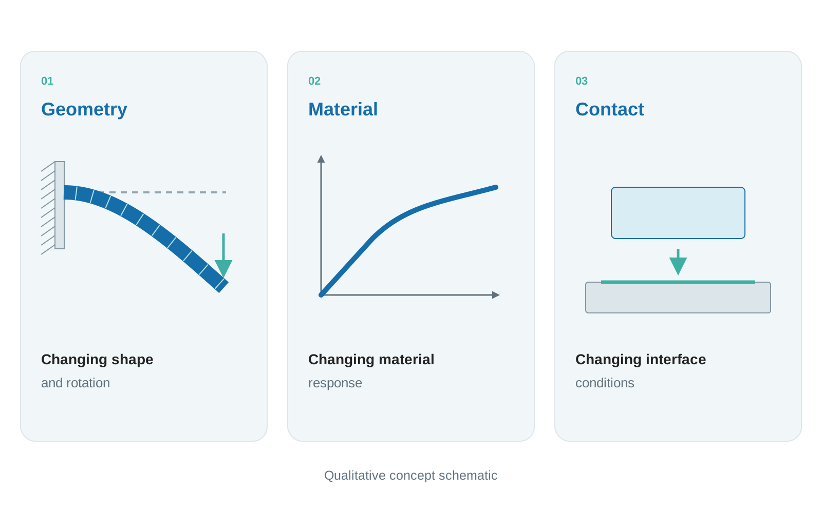
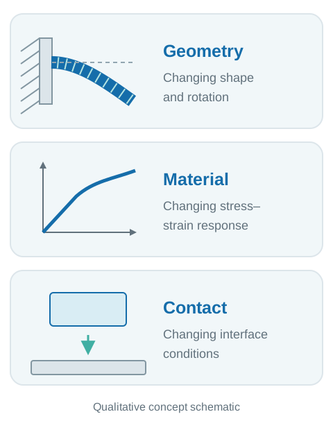
Concept schematic · not simulation results
- Case type
- Engineering methods
- Discipline
- Structural FEA
- Focus
- Geometry, material and contact
- Visuals
- Qualitative concept diagrams
01 / THE MODELLING QUESTION
Choose assumptions that represent the physical response
This GTS methods case study examines how geometric, material and contact changes affect a structural finite element analysis. The aim is to connect the expected behaviour of a component or assembly with the assumptions used in its model.
A linear analysis can provide a useful approximation when deformation is small, the material response is adequately linear and the boundary conditions remain unchanged. The decision to use nonlinear FEA begins with whether those assumptions remain suitable across the intended loading range.
The examples below are conceptual. They explain modelling decisions without assigning a client, load capacity or measured outcome to the illustrations.
02 / THREE MECHANISMS
Identify what changes during loading
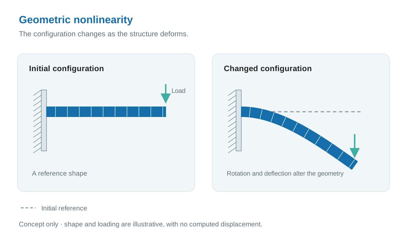
Geometric nonlinearity
Large deflections or rotations can change the geometry through which forces are carried. The analysis then needs to account for the deformed configuration when determining the structural response. This can matter even when the material remains linearly elastic.
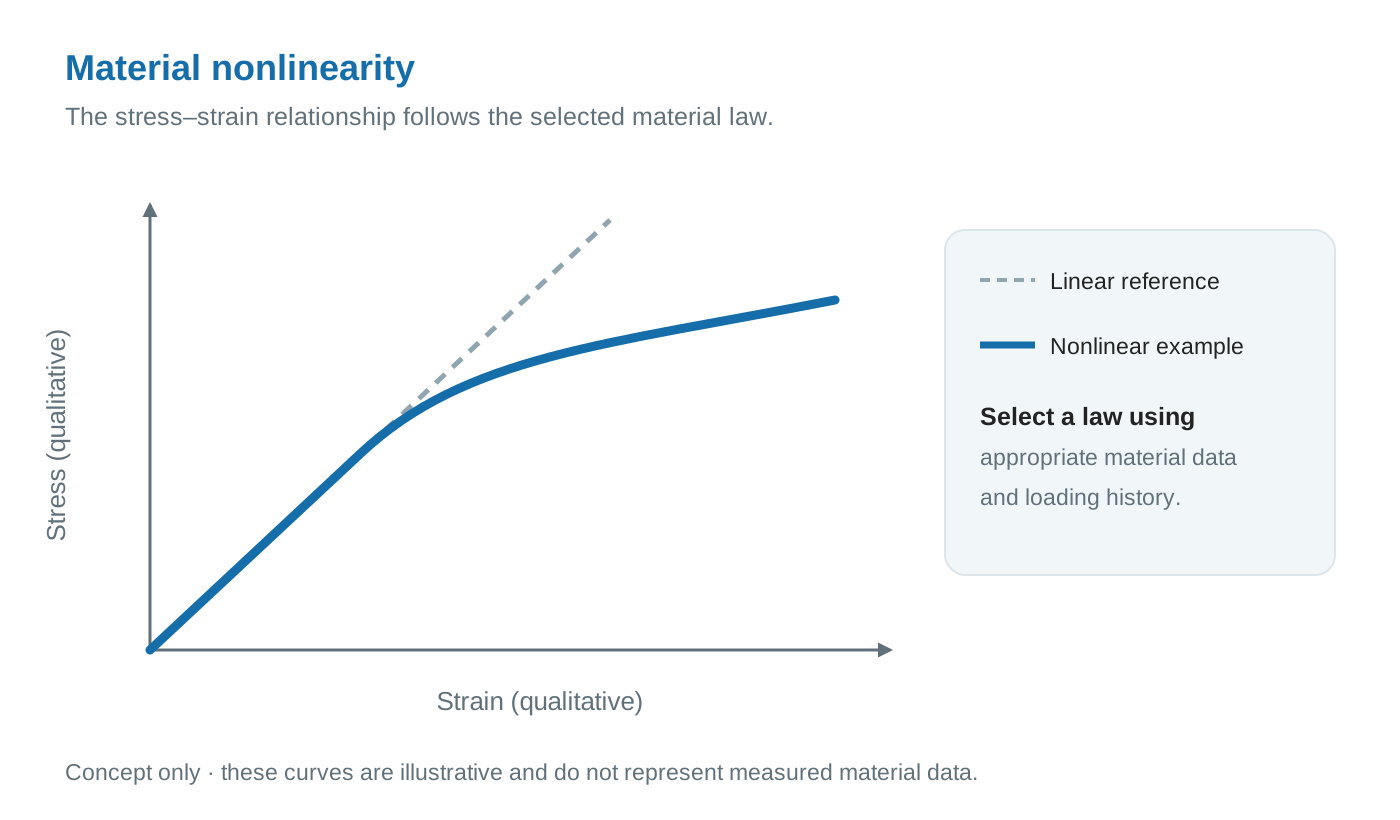
Material nonlinearity
The material may have a nonlinear relationship between stress and strain. Plastic yielding, nonlinear elasticity and nonlinear time-dependent behaviour require material descriptions suited to the mechanism and operating conditions. A nonlinear material response does not necessarily imply permanent deformation.
Contact nonlinearity
Interfaces can open, close or change their sliding state as loading develops. These changes alter how forces transfer between parts. Contact can be nonlinear even without friction; the change between separated and contacting surfaces is itself significant.
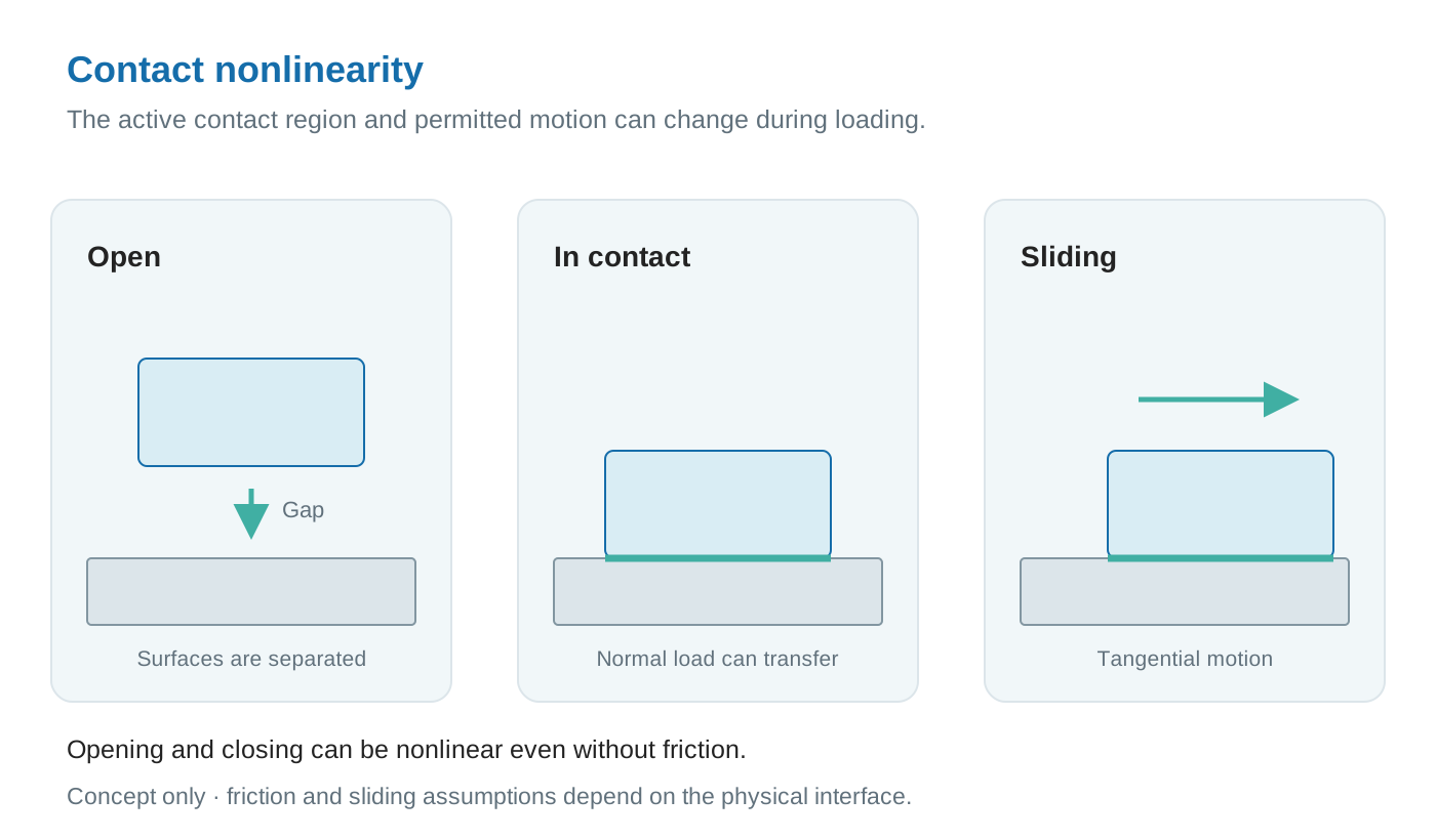
These mechanisms can occur together. A flexible assembly, for example, may change shape while its interfaces open or slide. The modelling approach should follow the mechanisms that influence the engineering decision.
03 / THE ASSESSMENT
Turn the mechanism into a model that can be checked
| What changes? | Modelling question | Evidence needed |
|---|---|---|
| Geometry | Does the deformed shape affect the load path? | Geometry, restraints and expected motion. |
| Material | Which constitutive behaviour matters? | Relevant material data and operating conditions. |
| Contact | Can interfaces separate, engage or slide? | Fit, gaps, preload and interface behaviour. |
For a nonlinear static assessment, loads or prescribed movements are commonly applied in increments, with iterations used to seek equilibrium at each step. The response can depend on the loading history, so the sequence of assembly, preload, loading and unloading may need to be represented.
Define the loading path
Establish the sequence, restraints and relevant nonlinear mechanisms.
Check the numerical solution
Review equilibrium, convergence and sensitivity to the mesh and increments.
Interpret the response
Examine deformation, stresses, strains and interface behaviour against the assessment criteria.
Numerical convergence is one check. Physical plausibility, suitable input data and sensitivity to modelling choices also matter. A converged calculation alone does not establish that the model represents the intended component or loading condition.
04 / ENGINEERING VALUE
Match the level of analysis to the design question
Nonlinear FEA allows changes in configuration, material response and interfaces to influence the predicted behaviour. Its value depends on choosing the relevant mechanisms and supplying the data needed to describe them.
Superposition does not generally apply to a nonlinear response. Scaling or adding linear results cannot represent changes such as yielding or the opening of a contact. Comparing suitable modelling assumptions can therefore be part of deciding how much analysis a design question needs.
Methods case-study scope
This page explains an assessment approach using qualitative diagrams. It contains no project-specific simulation or test results.
Graphler Technology Solutions
Engineering design, simulation and product development.
About our engineering team
YOUR NEXT ENGINEERING QUESTION
Define the right
FEA approach.
Share the component geometry, materials, loading sequence and interface conditions. We can help define a structural assessment around your design question.
Discuss a structural FEA projectExplore structural FEA services