FEA CASE STUDY/AGRICULTURAL STRUCTURES
FEA of a polyhouse frame and its stay-rope support
Assessing column movement under payload and wind loading, with the support conditions kept in view.
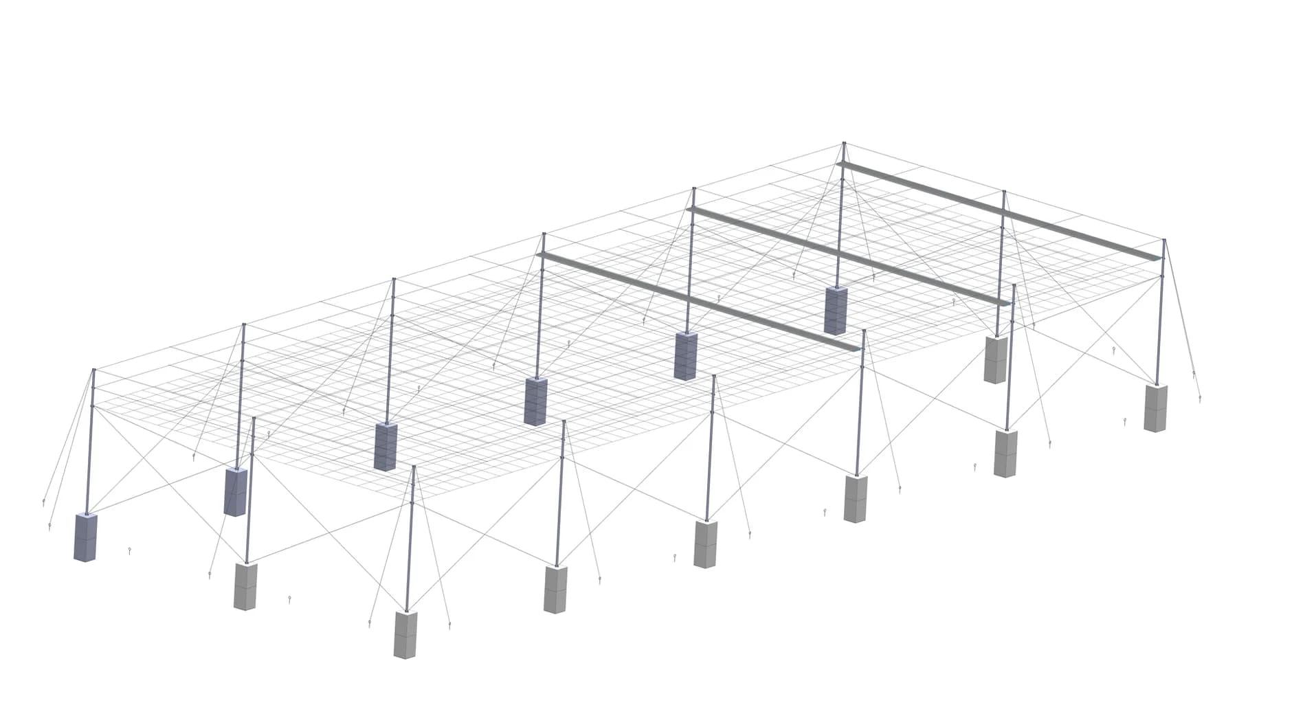
Original project geometry · columns and rope network
- Application
- Polyhouse structural frame
- Method
- Finite Element Analysis
- Load coverage
- 2 assessed load cases
- Key condition
- Assumed stay-rope tension
01 / THE CHALLENGE
Understand the frame together with its supports
Graphler Technology Solutions used Finite Element Analysis (FEA) to assess the vertical columns of a proposed polyhouse under two loading conditions: self-weight with payloads, and self-weight with wind loading on the columns.
The structure combined columns, an overhead wire-rope network and diagonal stay ropes. Its response therefore depended on both the applied loads and the support condition represented in the model.
The study examined stress and deformation in the columns and their connections. A central part of interpreting the results was the assumed tension in the stay ropes: the reported column movements were conditional on that tension being present.
02 / OUR APPROACH
Separate the payload and wind cases
GTS developed the finite element model from the supplied geometry and assigned the component material properties. The analysis then examined the two specified load combinations separately.
| Condition | What the model considered |
|---|---|
| 01 · Self-weight + payloads | The structure’s self-weight and payload loading associated with the wire-rope network. |
| 02 · Self-weight + wind | The structure’s self-weight and wind loading applied to the vertical columns, using a basic wind speed of 100 km/h. |
The wind case was defined around loading on the columns. The 100 km/h value describes the basic wind speed used for that calculation, rather than a verified wind-resistance rating for the complete covered polyhouse.
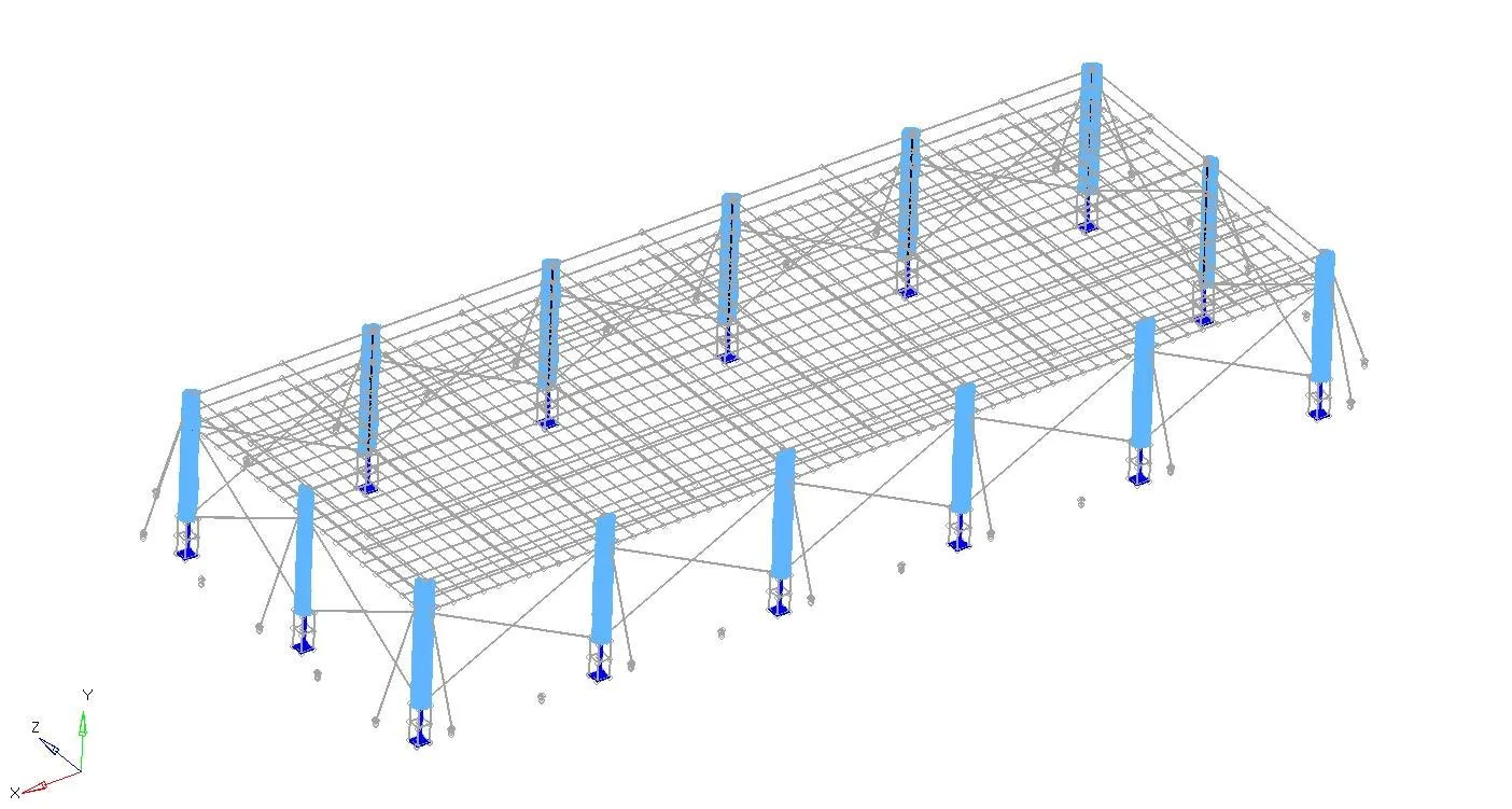
Represent the frame
Use the supplied geometry and component properties.
Define each load case
Assess the payload and column wind loads separately.
Read the response
Interpret column movement with the assumed rope tension.
03 / THE FINDINGS
Column movement depended on the support assumption
The report recorded a maximum column deformation of 11.19 mm for self-weight with payloads and 11.8 mm for self-weight with wind loading. These are predictions for two different load cases of the assessed structure.
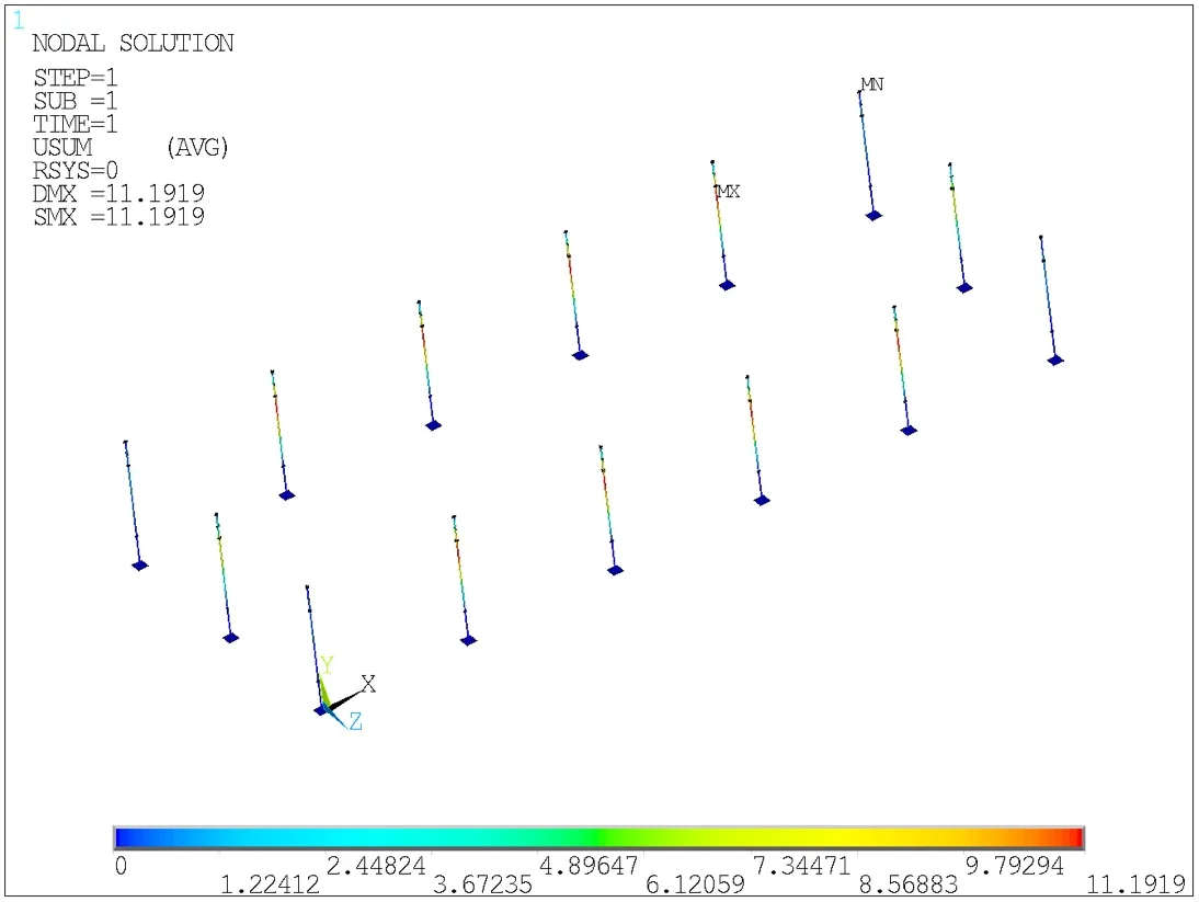
deformation
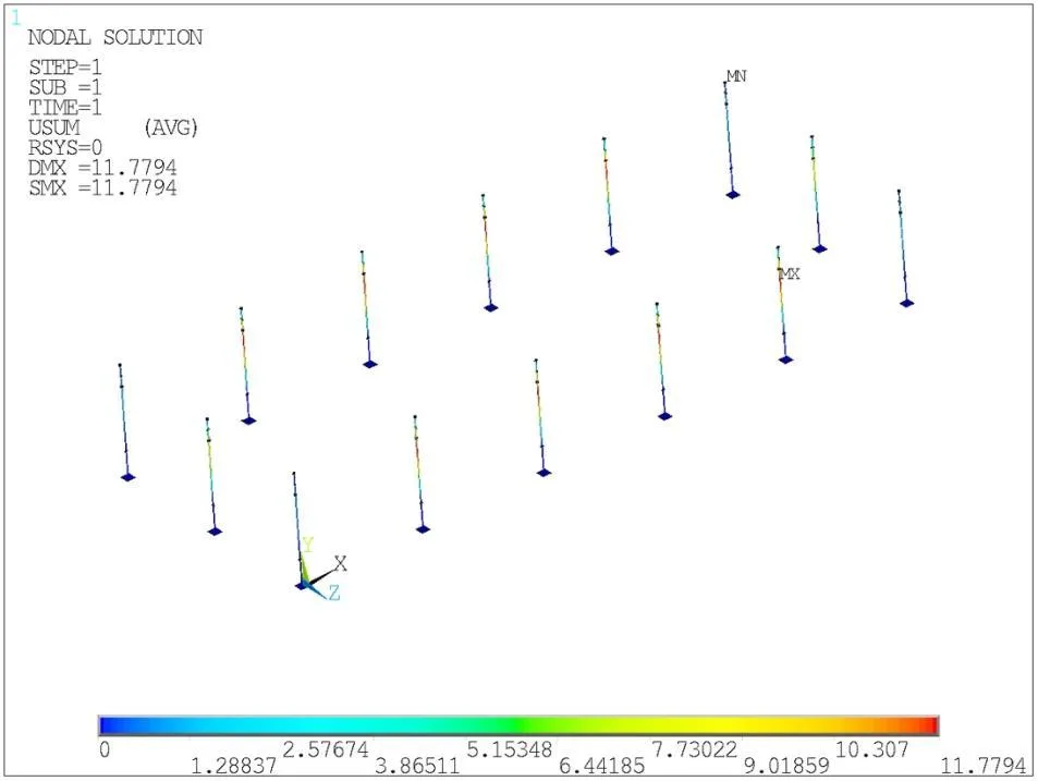
deformation
FIGURES 02–03Original column-deformation results. Each image retains its own legend and scale; the displayed figures above use the report’s rounded values. They are separate loading conditions, not a before-and-after design comparison.
The stay ropes must provide the assumed tension.
The report assumes that the stay ropes are tensioned to resist the applied loading associated with wire-rope self-weight and payload mass. It explicitly notes that lower tension may produce greater column deformation.The same qualification accompanies both load cases in the original report. It connects the numerical result to a specific support condition that needs to be understood when reviewing the design.
04 / ENGINEERING VALUE
Make the support condition part of the design discussion
The assessment provided deformation and stress results for the specified column load cases, while identifying stay-rope tension as a condition of the predicted response.
For the design team, the practical finding was the link between loading, rope support and column movement. The deformation values need to be considered alongside the model’s tension assumption when discussing how the structure is supported.
Assessment scope
These results are numerical predictions for the recorded geometry, loads and support assumptions. They do not establish a whole-polyhouse wind rating, a physical proof test or a fatigue-life prediction.
Graphler Technology Solutions
Engineering design, simulation and product development.
About our engineering team
YOUR NEXT ENGINEERING QUESTION
Understand the loads.
Define the supports.
Share the frame geometry, materials, payloads, wind-design inputs and support details. We can define a structural assessment around the conditions that matter to your project.
Discuss an FEA projectExplore FEA services