FEA CASE STUDY/PROCESS EQUIPMENT
FEA of a pressure-vessel skirt-to-head junction
Five load cases to examine how pressure, weight and lateral loads act at a critical supporting junction.
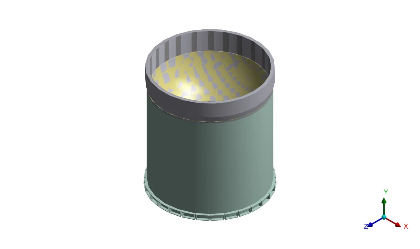
Original project geometry · lower vessel and skirt
How does the supporting junction respond to combined loads?
Explore the assessment- Application
- Pressure-vessel support junction
- Method
- Linear static FEA
- Load coverage
- 5 analysed scenarios
- Evaluation
- Stress classification lines
01 / THE CHALLENGE
Examine the junction that carries the vessel
Graphler Technology Solutions used Finite Element Analysis (FEA) to assess the connection between a pressure vessel’s bottom head and its supporting skirt. The study examined deformation and stress under empty, operating and hydrostatic-test conditions.
The junction brings together the curved pressure boundary and the cylindrical support. Internal pressure, vessel weight and lateral loads act through this region in different combinations. The engineering task was to examine those combinations and evaluate the resulting stresses at defined sections.
The assessment focused on the skirt-to-head assembly. Components outside the local model were represented through their mass contribution. A separate horizontal configuration represented the shop hydrotest condition.
02 / OUR APPROACH
Model the connection and its load cases
The three-dimensional assembly included the skirt, ring, bottom head and cladding. GTS used a solid-element model with linear-elastic material behaviour and bonded joints to examine the response under the specified loads.
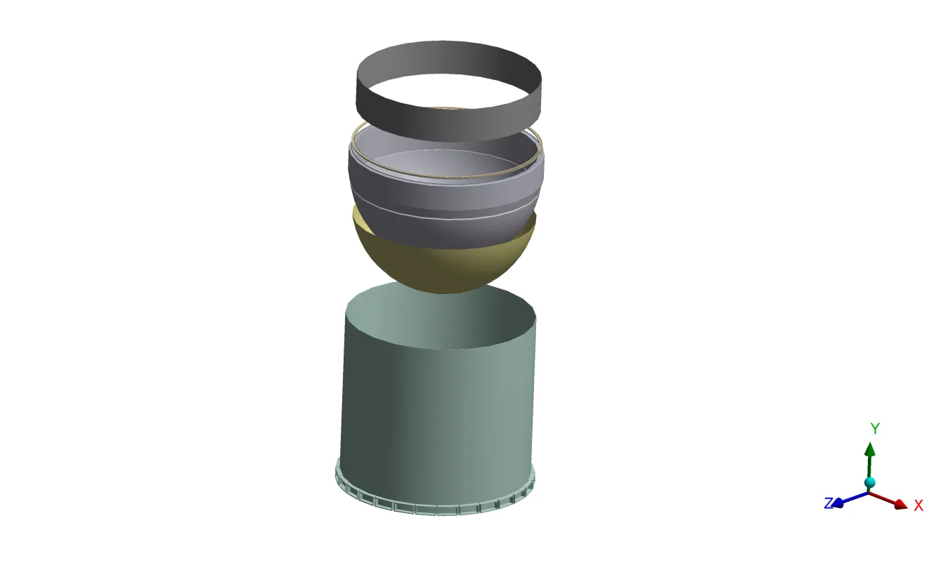
Five scenarios, with distinct operating conditions
The load cases combined internal pressure, the relevant vessel weight, and wind or seismic loading. The test cases also distinguished between vertical and horizontal arrangements.
| Condition | Applied load combination |
|---|---|
| 01 · Empty | Empty weight and wind; no internal pressure |
| 02 · Operating with wind | Maximum allowable working pressure, operating weight and wind |
| 03 · Operating with seismic load | Maximum allowable working pressure, operating weight and seismic loading |
| 04 · Vertical hydrotest | Hydrotest pressure and weight, with a reduced wind load |
| 05 · Horizontal hydrotest | Hydrotest pressure and weight, with a reduced wind load |
Support constraints were defined for the respective configurations. The analysis treated the material response as linear elastic and the connected weld regions as bonded.
Represent the assembly
Model the junction and the surrounding load path.
Apply the load cases
Resolve deformation and stress for each condition.
Classify the stresses
Evaluate sections at the junction, shell and skirt.
03 / THE ASSESSMENT
Connect the stress field to the evaluation sections
The operating case with seismic loading illustrates the local stress variation around the head-to-skirt region. The equivalent-stress contour identifies areas for closer examination within the assembly.
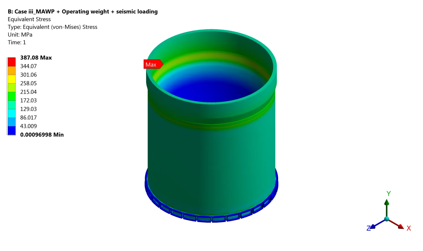
Evaluate membrane and bending stresses
The project report used the ASME Section VIII, Division 2, Part 5 Design by Analysis methodology for its stress evaluation. Stress Classification Lines (SCLs) were placed at three locations: the skirt-to-head junction, the shell and the skirt.
Stress integration along these lines separated the membrane and bending contributions for the section checks. The report recorded local membrane and combined membrane-plus-bending results by load case, providing a structured basis for comparison with its stated stress limits.
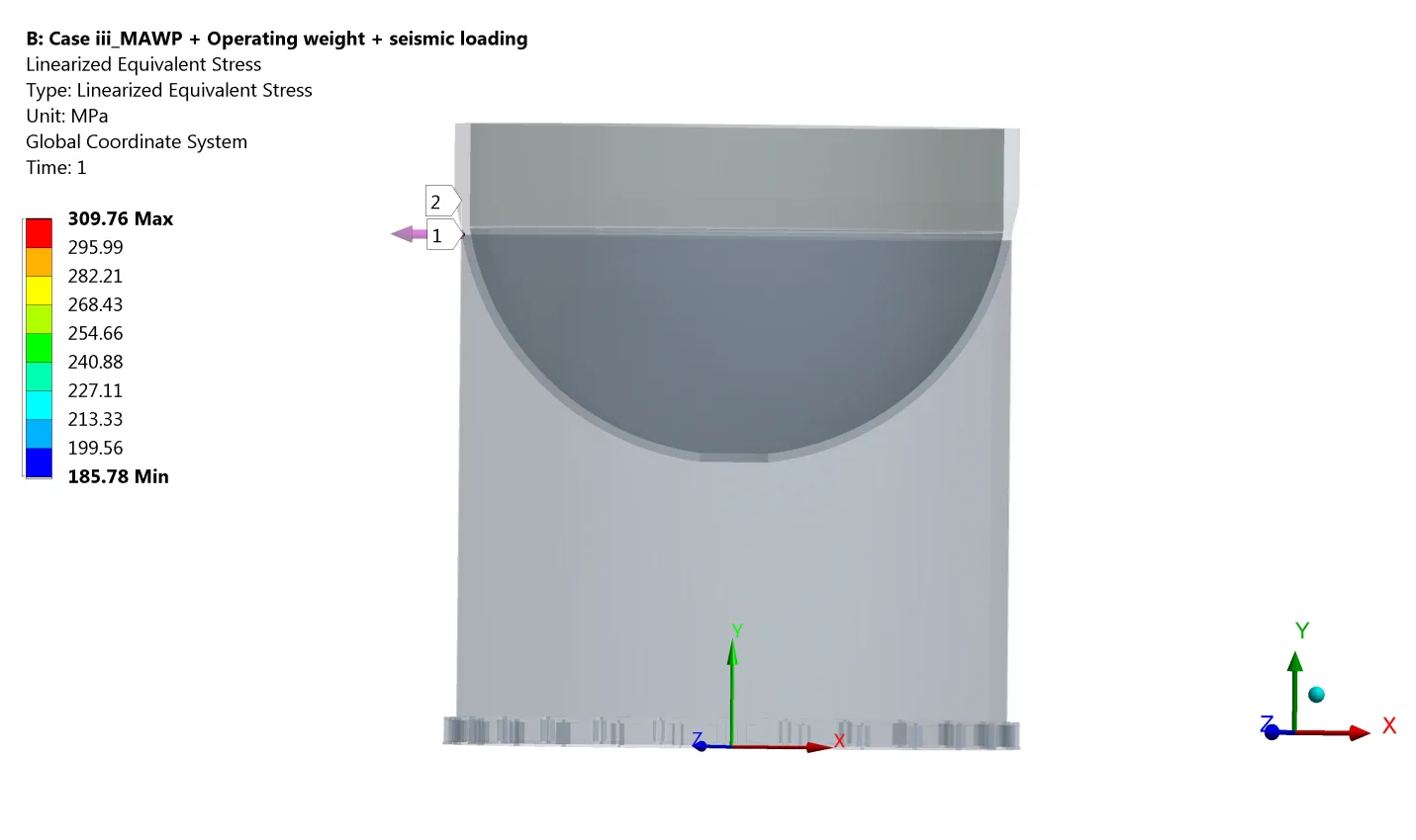
Read the contour together with the section results.
The stress field shows where the response varies. The SCL results distinguish the stress components used in the engineering assessment.04 / ENGINEERING VALUE
A traceable assessment of the supporting junction
The study brought together deformation results, stress contours and linearised section results for five load cases. It connected each operating or test condition to specific evaluation locations in the vessel assembly.
For the design team, this provided a documented basis for reviewing the junction, shell and skirt under the specified loading. The useful deliverable was the relationship between the geometry, load case and classified stress response.
Assessment scope
This case study describes a linear static assessment of the specified assembly and loads. Installation loads and operating vibration were outside the recorded scope. It does not establish whole-vessel certification or a fatigue-life prediction.
Graphler Technology Solutions
Engineering design, simulation and product development.
About our engineering team
YOUR NEXT ENGINEERING QUESTION
Understand the response
at a critical connection.
Share the vessel geometry, material details, load cases and design basis. We can define an FEA scope around the junctions and operating conditions that matter to your design.
Discuss an FEA projectExplore FEA services