CFD CASE STUDY/RENEWABLE ENERGY
Using CFD to assess wind forces on a single-axis solar tracker
Virtual wind-tunnel modelling to connect airflow, pressure distribution and structural loading.
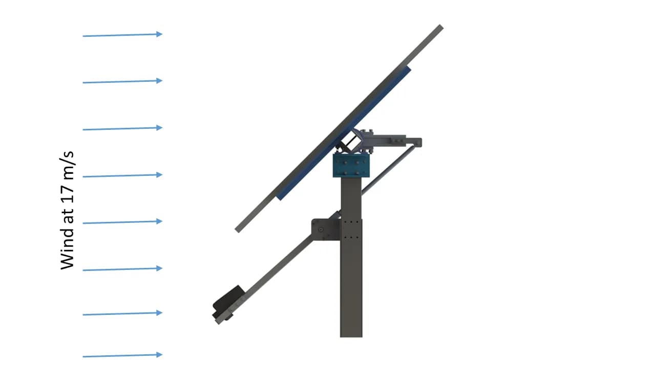
Original project geometry · 17 m/s wind condition
- Application
- Single-axis solar tracking
- Method
- CFD wind-tunnel modelling
- Featured condition
- 45° tilt · 17 m/s wind
- Engineering purpose
- Structural wind-load assessment
01 / THE CHALLENGE
Understand the load on a moving structure
Graphler Technology Solutions used Computational Fluid Dynamics (CFD) wind-tunnel modelling to investigate wind loading on a single-axis solar tracker. The assessment examined how the inclined modules affected the airflow and how pressure varied across the assembly.
A solar tracker changes its tilt to follow the sun. Its orientation to the wind therefore changes through operation, making the assessed position an essential part of any wind-load case.
The project connected a CFD assessment with finite element structural analysis. Wind-induced pressure fields were exported from the CFD model and mapped onto the structural model, providing spatially varying load inputs for the tracker assembly.
02 / OUR APPROACH
Place the tracker in a virtual wind tunnel
The wider assessment covered three wind cases. This case study focuses on the 45° configuration with a 17 m/s incoming wind shown in the project figures.
| Tracker position and wind direction | Assessed wind speed |
|---|---|
| Horizontal stow | 50 m/s |
| 45° tilt · East wind Featured case | 17 m/s |
| 45° tilt · West wind | 17 m/s |
These speeds define the analysed cases. They are not presented as certified operating limits or a verified stow-transition threshold.
Featured simulation setup
- Tracker tilt
- 45°
- Wind speed
- 17m/s
- Geometry scale
- 1:1full-scale model
The model represented the tracker and surrounding air using steady-state CFD at atmospheric conditions.
The full-scale virtual tunnel included space around the tracker and a boundary-layer representation of the incoming flow. GTS examined the flow around the inclined modules, the pressure field over their surfaces, and the associated loading for structural assessment.
Define the wind case
Tracker geometry, tilt and incoming flow.
Resolve the pressure field
Airflow and loading across the assembly.
Map loads to the structure
Export the pressure field to the finite element model.
The pressure-mapping step retained the spatial character of the aerodynamic loading for the structural analysis. The report also included the tracker's self-weight in its structural load assessment.
03 / THE FINDINGS
Pressure varied across the inclined modules
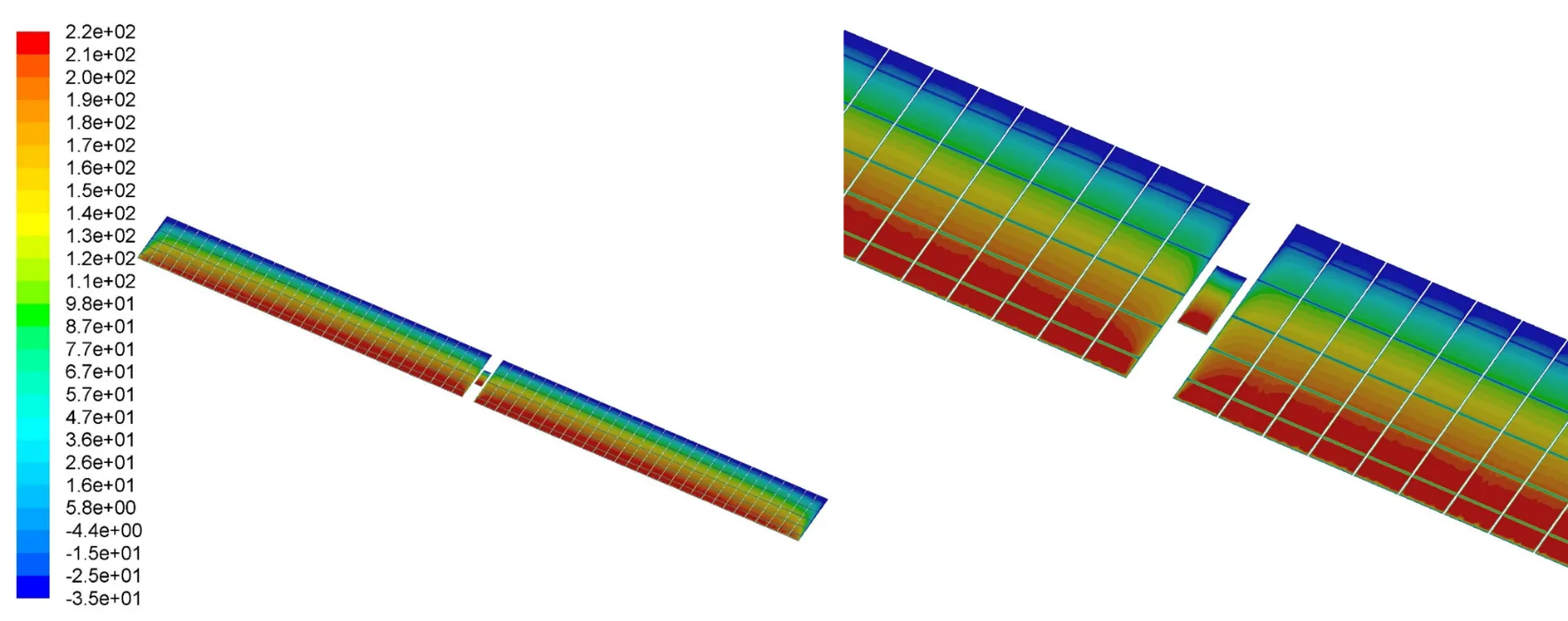
The predicted static-pressure contours showed a non-uniform distribution across the tracker modules. The full-assembly view and the close-up reveal how the pressure field changes over the module surface.
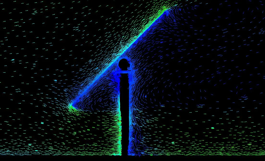
Flow around the tracker helps explain the loading
The velocity-vector view provides a complementary view of the airflow around the inclined panel and its support. Read together, the flow visualisation and pressure contours connect the surrounding air motion with the spatial loading on the geometry.
A pressure field is the starting point for a load case.
The aerodynamic result describes the loading on the tracker. Structural analysis addresses how the assembly responds. A pressure contour alone does not establish structural strength or safe operation.04 / ENGINEERING VALUE
Connect wind behaviour to component assessment
The assessment delivered spatial wind-pressure inputs for the structural model. This connected the CFD findings with the evaluation of the tracker components, including the posts, torque tube, rails and bearing assembly.
For a tracker project, this means defining each wind case around the relevant geometry, orientation and flow conditions, then carrying the resulting loads into the structural checks. The featured 45° case demonstrates that workflow.
Scope of the finding
The figures show steady-state numerical predictions for the evaluated configuration. They do not establish a universal worst-case tilt, a safe stow-transition speed, transient gust response, or validation against a physical wind-tunnel test.
Graphler Technology Solutions
Engineering design, simulation and product development.
About our engineering team
YOUR NEXT ENGINEERING QUESTION
Understand the wind
loads on your design.
Share the tracker geometry, operating positions, wind-design requirements and component details. We can define a CFD assessment that supports your structural engineering decisions.
Discuss a CFD projectExplore CFD services